Power grid control method and system with various load devices

A technology of load equipment and management and control system, applied in the direction of electrical components, circuit devices, etc., can solve problems such as low efficiency of power utilization, reduce experience, and tripping of electric switches, and achieve the effects of guaranteeing production, improving experience, and improving power utilization efficiency

Active Publication Date: 2014-07-23
BEIJING GUODIANTONG NETWORK TECH CO LTD +1
View PDF3 Cites 11 Cited by
  • Summary
  • Abstract
  • Description
  • Claims
  • Application Information

AI Technical Summary

Problems solved by technology

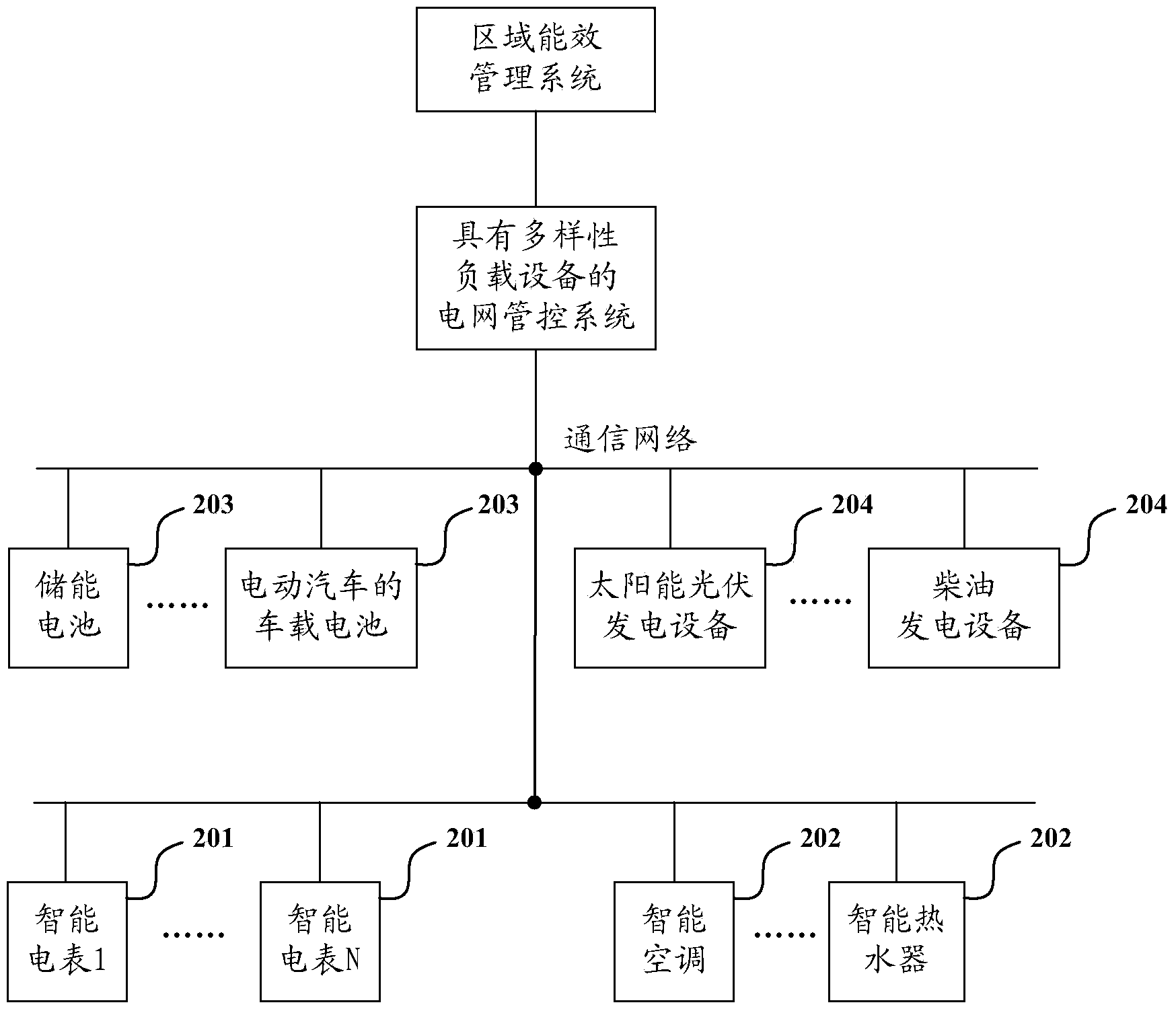
[0011] The inventors of the present invention found that with the development of the power grid, the existing power grid management and control system cannot meet the requirements of higher power utilization efficiency; the reason is that the energy storage equipment (such as batteries, electric vehicles) Power generation equipment (such as solar photovoltaic power generation equipment) is increasing; the existing power grid management and control system does not include energy storage equipment and power generation equipment on the user side, resulting in the gap between smart power consumption equipment, energy storage equipment and power generation equipment on the user side. prone to work inconsistency
For example, during the peak period of power consumption, the energy storage equipment on the user side is in the state of energy storage due to uncontrollable energy storage, which requires a large current supply, which can easily cause the switch on the user side to trip, resulting in the failure of the smart power consumption equipment and storage equipment on the user side. All functional equipment was forced to stop working
As a result, the smart electrical equipment, energy storage equipment, and power generation equipment on the user side do not work well, and the efficiency of power utilization is low, which reduces the user experience

Method used


Image

  • Power grid control method and system with various load devices
  • Power grid control method and system with various load devices
  • Power grid control method and system with various load devices

Examples


Embodiment Construction

[0049] In order to make the object, technical solution and advantages of the present invention clearer, the present invention will be described in further detail below with reference to the accompanying drawings and preferred embodiments. However, it should be noted that many of the details listed in the specification are only for readers to have a thorough understanding of one or more aspects of the present invention, and these aspects of the present invention can be implemented even without these specific details.

[0050] As used herein, terms such as "module" and "system" are intended to include computer-related entities such as, but not limited to, hardware, firmware, a combination of hardware and software, software, or software in execution. For example, a module may be, but is not limited to being limited to being, a process running on a processor, a processor, an object, an executable, a thread of execution, a program, and / or a computer. For example, both an applicatio...


PUM


Abstract

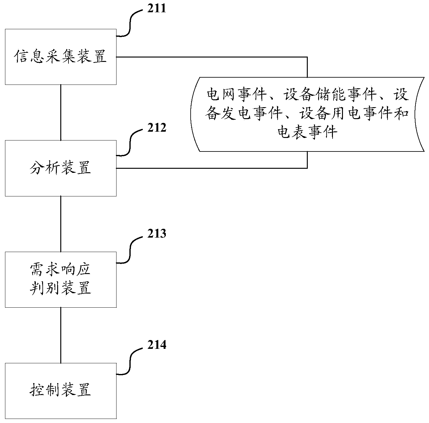
The invention discloses a power grid control method and system with various load devices. The control method comprises the steps that power grid information of a power grid is periodically collected by an information collection device, stamped with a timestamp and packaged as a power grid event, and electricity storage information of energy storage equipment is periodically collected by the information collection device, stamped with a timestamp and packaged as an equipment energy storage event; an analysis device analyzes the current power grid event to obtain the current load rate of the power grid, and the current load rate of the power grid is compared with a set load rate; the equipment energy storage event happening within a set time period after the current time is analyzed to obtain the current energy storage rate of the energy storage equipment, and the current energy storage rate of the energy storage equipment is compared with a set energy storage rate; a demand response judgment device combines analysis results into several combined results; for each combined result, if the combined result is judged to meet criteria, it is judged that a demand response opportunity is provided at present; a control device controls corresponding equipment. According to the technical scheme, the various load devices are controlled according to demand response opportunities, and the electric energy utilization efficiency can be improved.

Description

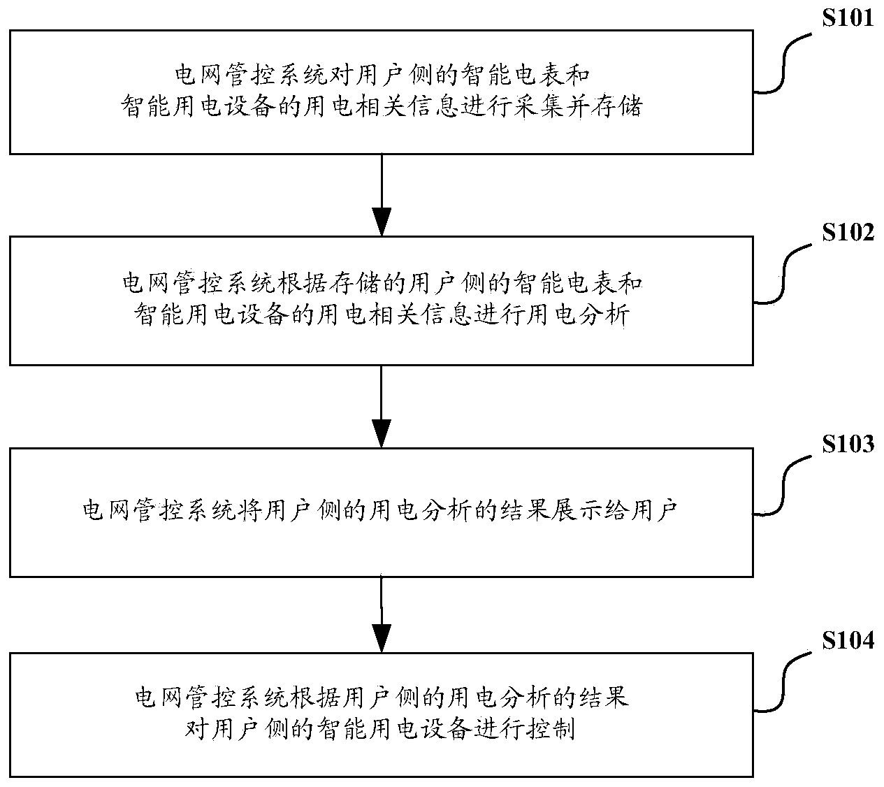
technical field [0001] The invention relates to the field of smart grid management, in particular to a management and control method and system for a grid with diverse load devices. Background technique [0002] With the development of my country's smart grid construction, power grid management and control systems have begun to be deployed on the user side of industrial and mining enterprises, office buildings, and residential buildings to manage smart meters and smart electrical equipment on the user side. The smart electrical equipment on the user side includes: smart appliances, smart home and security equipment. [0003] An existing power grid management and control system management and control method for smart meters and smart electrical equipment on the user side, the flow diagram of the management and control method is as follows figure 1 shown, including the following steps: [0004] S101: The power grid management and control system collects and stores power cons...

Claims


Application Information

Patent Timeline
Patent Type & Authority Applications(China)
IPC IPC(8): H02J13/00
Inventor 谢迎新王风雨伍亮闫爱梅李晓珍刘茵王茜
Owner BEIJING GUODIANTONG NETWORK TECH CO LTD
Why Eureka
Try Eureka