
Secondary ripple eliminating circuit of single-phase PWM rectifier

A secondary ripple and rectifier technology, applied in the direction of electrical components, output power conversion devices, etc., can solve problems such as adverse effects of converter efficiency, low DC voltage utilization, and reduced applicable range, etc., to increase the system The effect of failure probability, increased DC voltage utilization, and increased stability

Active Publication Date: 2014-07-23
SHANDONG UNIV
View PDF7 Cites 8 Cited by
  • Summary
  • Abstract
  • Description
  • Claims
  • Application Information

AI Technical Summary

Problems solved by technology

[0005] In the application document with the patent number CN201210545899.6, a PWM rectifier circuit secondary ripple elimination circuit using only four switching tubes is proposed, but the DC voltage utilization rate of this circuit is low, that is, the DC side voltage needs to be much higher than The peak value of the AC side voltage greatly reduces its applicable range and adversely affects the efficiency of the converter

Method used


Image

  • Secondary ripple eliminating circuit of single-phase PWM rectifier
  • Secondary ripple eliminating circuit of single-phase PWM rectifier
  • Secondary ripple eliminating circuit of single-phase PWM rectifier

Examples


Embodiment Construction

[0028] The present invention will be further described below in conjunction with the accompanying drawings and embodiments.

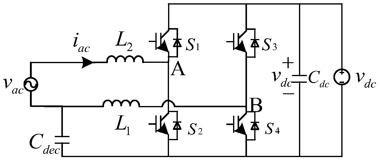
[0029] Such as Figure 4 As shown, a single-phase voltage type converter eliminates the secondary ripple circuit, which includes an AC side 1, a converter 2 and a DC side 3, the AC side 1 is connected to the converter 2 through an inductor, and the other part of the converter 2 One side is connected to the DC side 3.

[0030]The AC side 1 is divided into a first AC terminal and a second AC terminal. The converter 2 includes a capacitor bridge arm 4 connected in parallel, an A-phase bridge arm 5 and a B-phase bridge arm 6. The A-phase bridge arm 5 of the converter 2 is connected, the second AC terminal is connected to the capacitor bridge arm 4, and the capacitor bridge arm 4 is connected to the B-phase bridge arm 6 through the inductor L1. The AC side includes an AC power source or load 7 , one side of the AC power source or load 7 is connected to the...


PUM


Abstract

The invention discloses a secondary ripple eliminating circuit of a single-phase PWM rectifier. The secondary ripple eliminating circuit comprises an alternating current side, a converter and a direct current side, the alternating current side is connected with the converter through an inductor, the other side of the converter is connected with the direct current side, a capacitor C2 is connected to the input end of the alternating current side and the negative electrode end of the direct current side, and a capacitor C1 is connected to the input end of the alternating current side and the positive electrode end of the direct current side. According to the secondary ripple eliminating circuit, compared with an original H bridge converter, a filter inductor on the alternating current side is divided into two parts, a capacitor bridge arm is additionally arranged, secondary ripple power is absorbed, the direct-current bus voltage supporting effect is achieved, and therefore the aims of reducing secondary ripples on the direct current side and replacing an original large capacitor on the direct current side are achieved.

Description

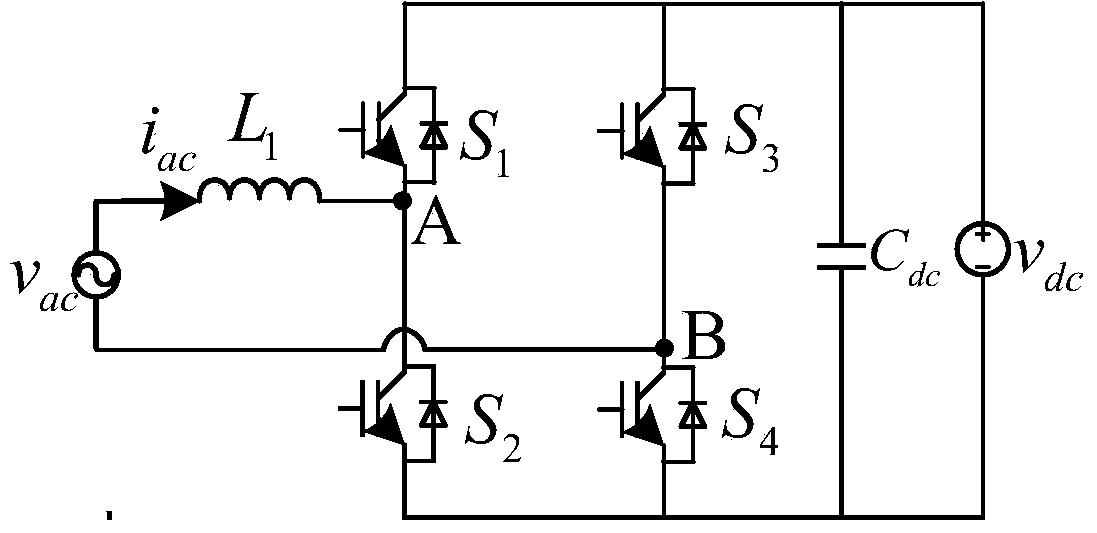
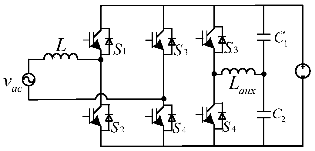
technical field [0001] The invention relates to a single-phase PWM rectifier circuit for eliminating secondary ripples. Background technique [0002] In small and medium power applications, single-phase PWM rectifiers are widely used. The most widely used PWM rectifiers are figure 1 The H-bridge converter shown, but when the AC side voltage is AC and the input current is AC with the same frequency, the DC side will generate secondary ripples, which will affect the power quality of the DC side, the stability of the system, and the DC The service life of side equipment, etc. will cause adverse effects. The traditional solution is to connect a very large capacitor C in parallel on the DC side dc , used to suppress the secondary ripple, but this method will increase the volume of the entire converter, increase the cost, and greatly reduce the power density of the system. Moreover, this method can only suppress but not eliminate the secondary ripple on the DC side. When the v...

Claims


Application Information

Patent Timeline
Patent Type & Authority Applications(China)
IPC IPC(8): H02M1/14
Inventor 王辉漆文龙
Owner SHANDONG UNIV
Learn More