
Low-input-current-ripple single-switch high-gain converter

A technology of current ripple and single switch, which is applied in the direction of converting DC power input to DC power output, adjusting electrical variables, and output power conversion devices, and can solve problems such as large input current ripple and large input current ripple , to achieve low input current ripple, increase output voltage gain, and reduce the number of switches

Inactive Publication Date: 2014-07-23
ANHUI UNIVERSITY OF TECHNOLOGY
View PDF6 Cites 6 Cited by
  • Summary
  • Abstract
  • Description
  • Claims
  • Application Information

AI Technical Summary

Problems solved by technology

[0003] Regarding the structural design of a single-switch converter with high gain, related technical solutions have been disclosed in the prior art, such as: Chinese Patent No. 201310423314.8, the name of the invention is: a single-switch high-gain boost converter, described The single-switch high-gain boost converter includes a common Boost circuit link and an energy storage circuit link; the common Boost boost circuit link includes a DC voltage source (V g ), the first inductance (L 1 ), the fourth diode (D 4 ), the fourth capacitor (C 4 ) and the output load (R L ); the energy storage circuit link includes the first diode (D 1 ), the second diode (D 2 ), the third diode (D 3 ), the first capacitor (C 1 ), the second capacitor (C 2 ), the third capacitor (C 3 ), the second inductance (L 2 ) and the third inductor (L 3 ), although the application scheme improves the input voltage gain, but the input current ripple is relatively large
[0004] In addition, for the Chinese patent number ZL201320524859.3, the name of the invention is: a two-winding coupled inductance voltage doubler type single-switch high-gain converter, the input current ripple of this technical solution is relatively large

Method used


Image

  • Low-input-current-ripple single-switch high-gain converter
  • Low-input-current-ripple single-switch high-gain converter
  • Low-input-current-ripple single-switch high-gain converter

Examples


Embodiment 1

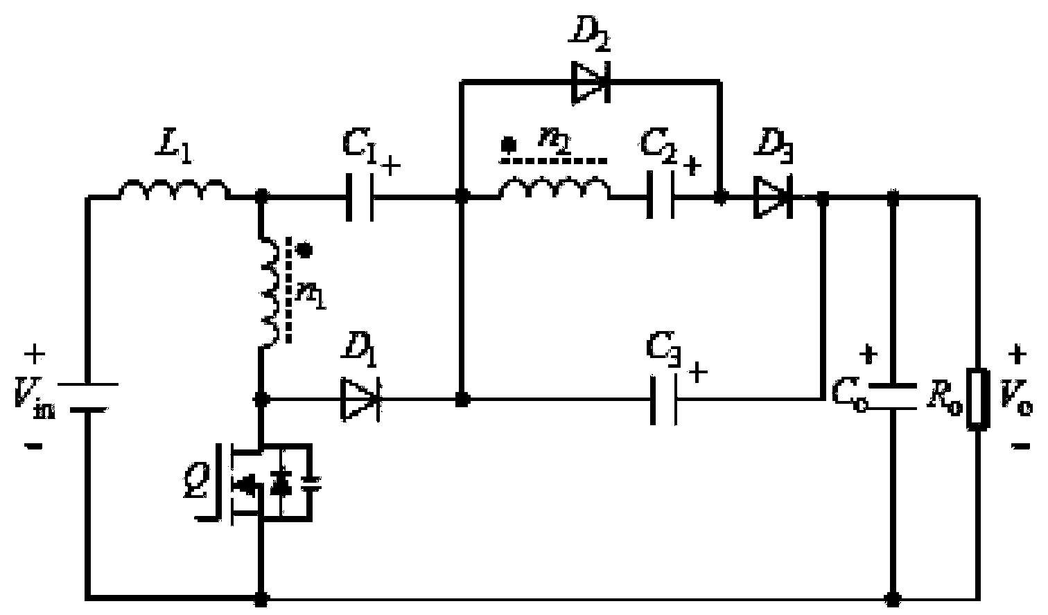
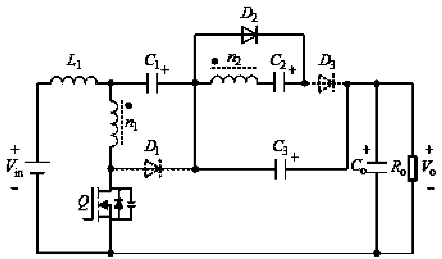
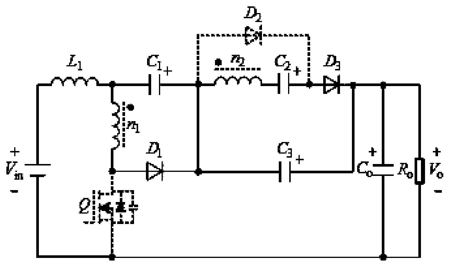
[0027] Such as figure 1 shown, a low input current ripple single-switch high-gain converter, including a DC input source V in , independent boost inductor L 1 , a controllable power switch tube Q with a first winding n 1 and the second winding n 2 of the coupled inductor, the clamping diode D 1 , the clamp capacitor C 1 , the first unidirectional rectifier diode D 2 , the second unidirectional rectifier diode D 3 , voltage doubling capacitor C 2 , storage capacitor C 3 and output filter capacitor C o ;

[0028] DC input source V in The positive and negative poles are respectively connected with the independent boost inductor L 1 One end of the power switch tube Q is connected to the source, and the independent boost inductor L 1 The other end of the coupled inductor with the first winding (n 1 ) of the same name and the clamping capacitor C 1 One end of the coupled inductor is connected to the first winding n of the coupled inductor 1 The other end and the drain...


PUM


Abstract

The invention discloses a low-input-current-ripple single-switch high-gain converter which comprises a direct-current input source (Vin), an independent boost inductor (L1), a controllable power switch tube (Q), a coupling inductor provided with a first winding (n1) and a second winding (n2), a clamping diode (D1), a clamping capacitor (C1), a first one-way rectifier diode (D2), a second one-way rectifier diode (D3), a voltage-multiplying capacitor (C2), an energy-storage capacitor (C3) and an output filter capacitor (Co). Compared with traditional Boost converters, the low-input-current-ripple single-switch high-gain converter can utilize the coupling inductor to improve output voltage gain, can reduce crest voltage stress of the power switch tube and the diode and has the advantage of being low in input current ripple, and the overall conversion efficiency of the converter is improved.

Description

technical field [0001] The invention relates to a DC-DC converter in the field of power electronics, in particular to a single-switch high-gain converter with low input current ripple. Background technique [0002] DC-DC boost converters have received more and more research and application in photovoltaic or fuel cell grid-connected power generation systems. For new energy sources such as photovoltaics and fuel cells, the input current ripple has a greater impact on their power generation efficiency. Therefore, , the input current continuous low ripple, high boost gain converter topology becomes the first choice. The conventional boost converter proposes limited boost gain, the voltage stress of the switching tube is large, the switching loss is large, the reverse recovery current of the diode is large, and the reverse recovery loss is large, which will reduce the DC-DC The conversion efficiency of the boost converter. Large input current ripple shortens the service life o...

Claims


Application Information

Patent Timeline
Patent Type & Authority Applications(China)
IPC IPC(8): H02M3/335H02M1/14
Inventor 胡雪峰王琳章家岩代国瑞
Owner ANHUI UNIVERSITY OF TECHNOLOGY
Learn More