Micro tillage machine with double rotary tiller shaft and speed control lever

A technology of speed control and micro-tiller, which is applied in the field of micro-tiller, and can solve the problem that the machine can no longer continue to work.

Inactive Publication Date: 2016-08-24
广西万里顺机械制造有限公司
View PDF5 Cites 0 Cited by
  • Summary
  • Abstract
  • Description
  • Claims
  • Application Information

AI Technical Summary

Problems solved by technology

When these two types of micro-tillers are working, once there is a problem with the rotary tillage or one of the driving components, the whole machine will no longer be able to continue to work.

Method used


Image

  • Micro tillage machine with double rotary tiller shaft and speed control lever
  • Micro tillage machine with double rotary tiller shaft and speed control lever
  • Micro tillage machine with double rotary tiller shaft and speed control lever

Examples


Embodiment 1

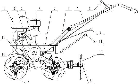
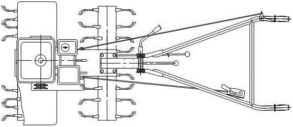
[0025] Embodiment 1, the complete machine structure of the present invention is as figure 1 figure 2 As shown, the power mechanism (1) is installed in front of the gearbox body assembly (5), the front rotary tiller (13) is installed in front of the gearbox body assembly (5), and the rear of the gearbox body (18) Armrest mounting seat (6) is installed, armrest frame (7) is installed above the armrest mounting seat (6), and rear rotary tiller (11) and speed control mechanism (12) are installed at the rear.

Embodiment 2

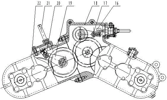
[0026] Embodiment 2, the power device (1) transmits the power to the pulley (2) through the V-belt (3), and the pulley (2) drives the I shaft (25) and the I-II gear (24) on the I shaft to rotate, The Ⅰ-Ⅱ gear (24) transmits power to the Ⅱ shaft Ⅰ gear (26) on the Ⅱ shaft (27), the Ⅱ shaft Ⅱ gear (29) and the Ⅱ shaft transmission gear (28), and then the Ⅱ shaft transmission gear (28) is transmitted to the Ⅲ-axis large gear (30) and the Ⅲ-axis pinion (31), and then transmitted to the Ⅳ-axis double gear (32) by the Ⅲ-axis pinion (31), and the Ⅳ-axis double gear (32) Sent to the rear rotary tiller gear (34) and rotary tiller shaft (35) to make the rear rotary tiller work.

[0027] The power transmission route of the front rotary tillage part is: the power is transmitted to the second gear (29) of the third shaft, and the second gear (29) of the second shaft is transmitted to the rotary tiller transmission gear on the separation drive shaft (38). (37), at this time, if the shiftin...

Embodiment 3

[0029]Embodiment 3, a micro tillage machine with double rotary tiller shafts and speed control levers, including a power mechanism, a pulley, a V-belt, a belt cover, a gearbox body assembly, an armrest mounting seat, an armrest frame, a clutch handle, and a rotary tiller clutch Handle, variable speed handle, rear rotary tiller assembly, speed control mechanism, front rotary tiller assembly, fender bracket, frame, variable speed fork, variable speed fork shaft, gearbox body, front rotary tiller Gear shift fork, front rotary tillage fork shaft, welding parts of clutch shift fork lever, front rotary tiller box, belt pulley, Ⅰ-Ⅱ gear, Ⅰ shaft, Ⅱ shaft Ⅰ gear, Ⅱ shaft, Ⅱ shaft transmission gear , Ⅱ shaft gear Ⅱ, Ⅲ shaft large gear, Ⅲ shaft pinion gear, Ⅳ shaft dual gear, Ⅳ shaft, rotary tillage gear, rotary tillage shaft, gear gear, rotary tillage transmission gear, separation drive shaft, Ⅲ shaft, It is characterized in that: 1) The gearbox body assembly (5) is a herringbone struc...


PUM


Abstract

The invention discloses a mini-tiller with double rotary cultivation shafts and a speed control rod. The mini-tiller is characterized in that a motive power mechanism is arranged in front of a position above a gearbox body assembly, a rotary cultivation cutter assembly is arranged in front of the gearbox body assembly, an armrest installing sat is arranged behind a position above a gearbox body, an armrest frame is arranged on the armrest installing seat, and a postpositive rotary cultivation cutter assembly and a speed control mechanism are arranged at the back side. The mini-tiller has the advantages that the gearbox body is of a herringbone-shaped structure, the postpositive rotary cultivation cutter assembly is arranged behind the herringbone-shaped structure, the prepositive rotary cultivation cutter assembly is arranged in front of the herringbone-shaped structure and is provided with a rolling rake tool and a plough tool. During the operation in the paddy field, the postpositive and prepositive rotary cultivation cutter assemblies are utilized for completing the matching with a speed control device, a paddy field mouse cage type field rolling wheel can also be replaced at the postpositive rotary cultivation cutter assembly, other matching is unchanged, the paddy field rotary cultivation work is completed, during the operation in the dry field, the mini-tiller is matched with the speed control device to work, the efficiency is high, the operation is convenient, the functions are many, the application range is wide, the cost is low, the oil consumption is low, and the physical work is reduced.

Description

technical field [0001] The invention belongs to the field of agricultural machinery, in particular to a micro tillage machine with double rotary tiller shafts and speed control rods. Background technique [0002] The structure of the existing micro-tillers is that the rotary tiller is directly installed on the drive shaft. When the machine is working, the rotary tiller plays two functions of walking and digging, and some tillers with rotary tillers have two functions: The functions of walking and digging are completed by the drive shaft and the rotary tiller shaft respectively. Due to structural reasons, the power output shaft of the gearbox is prone to failure or failure, resulting in product quality problems. [0003] Most of the micro-tillers on the market have the following two forms in structure: the first one is to install the rotary tiller directly on the drive shaft. Two functions of soil; the second is that the shaft of the rotary tiller is installed separately fro...

Claims


Application Information

Patent Timeline
Patent Type & Authority Patents(China)
IPC IPC(8): A01B33/02A01B33/08A01B49/02
Inventor 曾宪泽
Owner 广西万里顺机械制造有限公司
Why Eureka
Try Eureka