Automatic tube feeding multi-cutter tube cutting device of bearing steel tube

A technology for bearing steel pipes and feeding pipes, which is applied in the direction of pipe shearing devices, shearing devices, and accessories of shearing machines, etc. It can solve the problems of increased processing costs, inability to guarantee the accuracy of parts, and low production efficiency, so as to improve work efficiency, Guaranteed quality effect

Active Publication Date: 2014-07-30
新昌新天龙纽尚精密轴承有限公司
View PDF14 Cites 9 Cited by
  • Summary
  • Abstract
  • Description
  • Claims
  • Application Information

AI Technical Summary

Problems solved by technology

[0002] Bearings are used in a wide range of applications, especially in the automotive industry, where the demand is great. The outer casing of the bearing is to cut the steel pipe into the required length, and then process it with a machine tool. The pipe feeding mechanism sends a section of pipe forward, and the pipe cutting knife After cutting, the pipe delivery mechanism will send another section, and the process is constantly reciprocating. Each time the pipe delivery mechanism sends a certain length of bearing steel pipe, it can only cut once, and only one section can be cut at a time. There is no automatic pipe delivery mechanism on traditional machine tools. The production of enterprises The efficiency is very low, the manual labor intensity is very high, and the accuracy of the parts cannot be guaranteed, which increases the processing cost in the later stage, the effective utilization rate of the equipment is low, and the kinetic energy consumption is large. At present, some enterprises have developed a machine tool with a high degree of automation. mechanism, but the structure is complicated and the cost is high. The market needs an automatic pipe cutting equipment with simple structure, low cost and high efficiency.

Method used


Image

  • Automatic tube feeding multi-cutter tube cutting device of bearing steel tube
  • Automatic tube feeding multi-cutter tube cutting device of bearing steel tube
  • Automatic tube feeding multi-cutter tube cutting device of bearing steel tube

Examples


Embodiment Construction

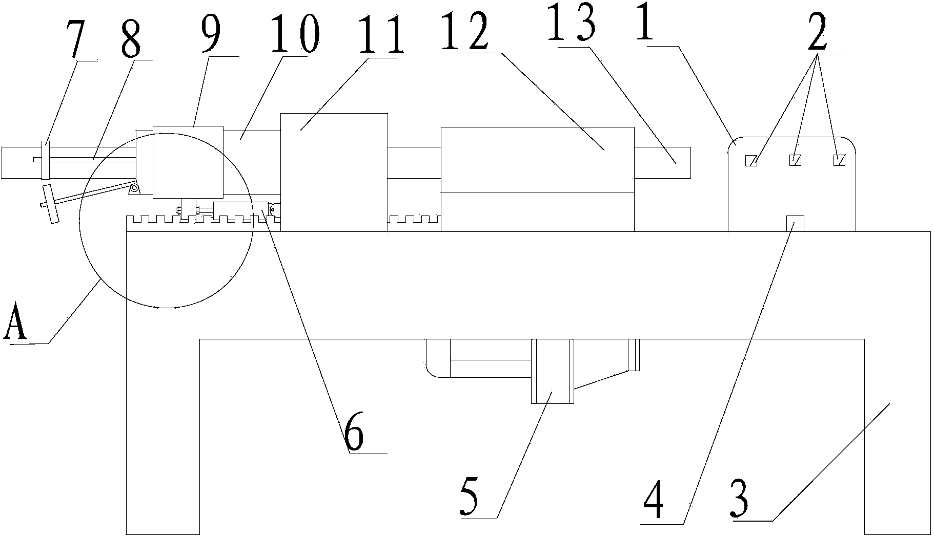
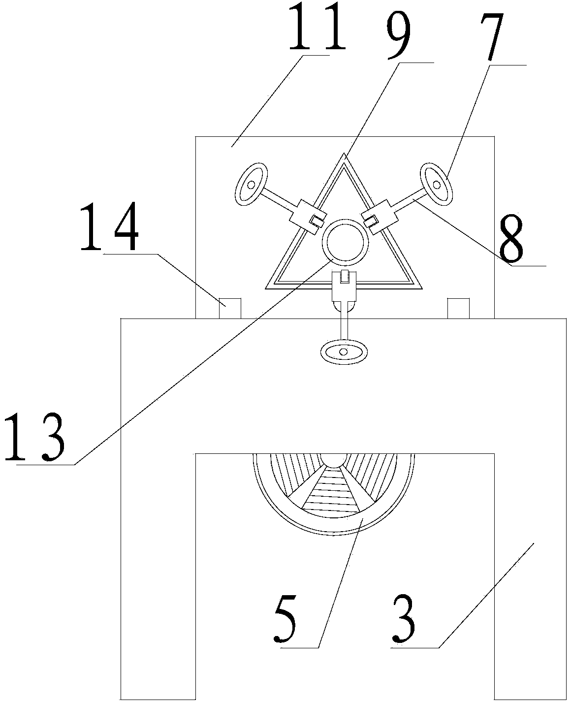
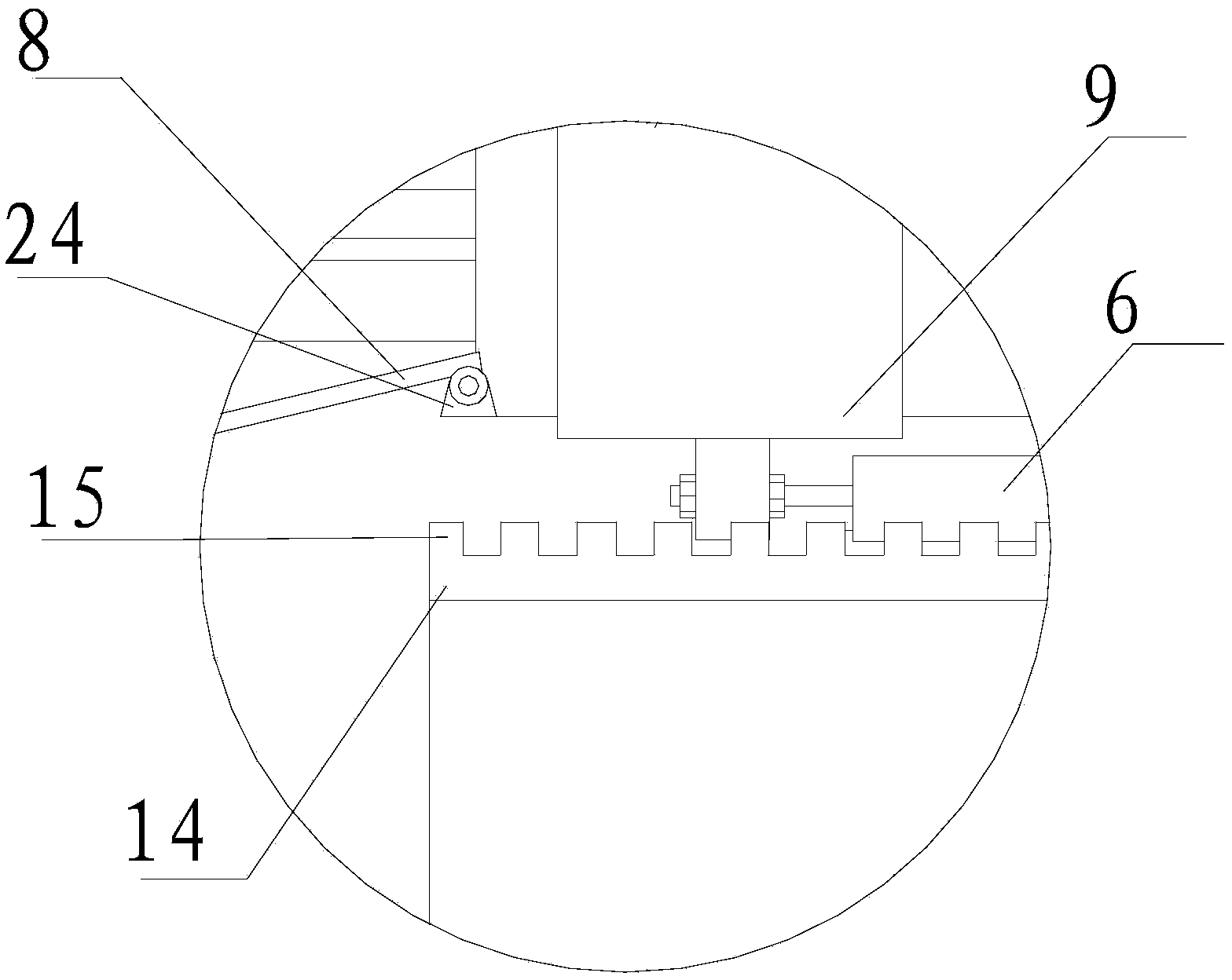
[0020] Refer to figure 1 , figure 2 , image 3 , Figure 4 , Figure 5 , The present invention is an automatic pipe feeding and multi-knife pipe cutting device for bearing steel pipes, which includes a worktable 3, a tool post 1, a tool post track 4 and a toothed track 14. The toothed track 14 is installed on the worktable 3 and the toothed track 14 A pipe-feeding seat 11 is installed, the pipe-feeding seat 11 is installed in cooperation with the triangle seat 10, the triangle seat 10 is installed in cooperation with the clamping sleeve 9, and the triangle seat 10 is installed with a clamping shaft 8, the clamping shaft 8 A clamping wheel 7 is installed at the end of the tool, a rotating tube seat 12 is installed on the worktable 3, the tool holder rail 4 is installed on the worktable 3, and a tool holder 1 is installed on the tool holder rail 4. Several pipe cutters 2 are installed on 1. There are 3 pipe cutting knives 2, 3 pipe cutting knives 2 are sequentially installed on...


PUM


Abstract

The invention discloses an automatic tube feeding multi-cutter tube cutting device of a bearing steel tube. The automatic tube feeding multi-cutter tube cutting device comprises a workbench, a tool holder, a tool holder track and a tooth track, wherein the tooth track is mounted on the workbench, a tube feeding base is mounted on the tooth track, and the tube feeding base and a triangular base are mounted in a matching manner, the triangular base and a clamping sleeve are mounted in the matching manner, clamping shafts are mounted on the triangular base, clamping wheels are mounted at the tail ends of the clamping shafts, a rotary tube socket is mounted on the workbench, the tool holder track is mounted on the workbench, the tool holder is mounted on the tool holder track, and a plurality of tube cutters are mounted on the tool holder. The automatic tube feeding multi-cutter tube cutting device of the bearing steel tube disclosed by the invention can improve the work efficiency, save energy and lower the investment cost of equipment, and further is simple in structure, convenient in maintenance, low in cost and high in efficiency.

Description

【Technical Field】 [0001] The invention relates to the technical field of pipe cutting machines, in particular to the technical field of a multi-knife pipe cutting device for automatic pipe feeding of bearing steel pipes. 【Background technique】 [0002] The application range of bearings is very wide, especially in the automotive industry, where the demand is great. The outer shell of the bearing is to cut the steel pipe to the required length and then process it with a machine tool. The pipe feeding mechanism sends a section of pipe forward and the pipe cutter After the cut, the pipe feeding mechanism sends another section. The process continues to reciprocate. The pipe feeding mechanism can only cut a certain length of bearing steel pipe each time, and only one section at a time. There is no automatic pipe feeding mechanism on traditional machine tools. The efficiency is very low, the manual labor intensity is very large, and the accuracy of the parts cannot be guaranteed, which ...

Claims


Application Information

Patent Timeline
Patent Type & Authority Applications(China)
IPC IPC(8): B23D21/00B23D33/02
Inventor 周国良
Owner 新昌新天龙纽尚精密轴承有限公司
Why Eureka
Try Eureka