Optical glass automatic installing device for triangular laser gyroscope
An automatic assembly device and optical lens technology, applied in the direction of assembly machines, metal processing equipment, manufacturing tools, etc., can solve the problems of poor assembly consistency and low efficiency, and achieve the effects of good consistency, high motion resolution, and convenient control
- Summary
- Abstract
- Description
- Claims
- Application Information
AI Technical Summary
Problems solved by technology
Method used
Image
Examples
Embodiment 1
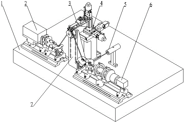
[0027] refer to figure 1 , the triangular laser gyro optical lens automatic assembly device consists of a marble vibration isolation table 1, an incident laser acquisition system 2, a lens clamping manipulator with a force sensor 3, an optical lens position automatic adjustment unit 4, a photoelectric detection unit 5, and spot image detection Unit 6, laser gyro cavity positioning unit 7; the incident laser acquisition system 2, optical lens position automatic adjustment unit 4, photoelectric detection unit 5, spot image detection unit 6 and laser gyro cavity positioning unit 7 are all composed of bolts It is fixed on the marble vibration isolation table 1, and the positional relationship is determined by the optical path. The lens clamping manipulator (3) with force sensor is fixed at the end of the optical lens position automatic adjustment unit 4.
Embodiment 2
[0028] Embodiment Two: This implementation example is basically the same as Embodiment One, and the special features are as follows:
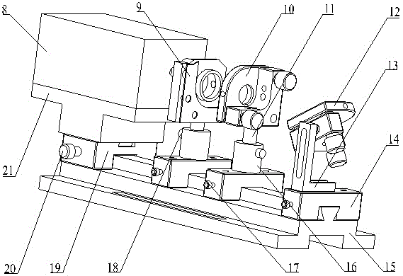
[0029] refer to figure 1 , figure 2 The above-mentioned incident laser acquisition system 2 is composed of a laser generator 8, a light adjustment lens and its mounting frame 9, a polarizing lens and its mounting frame 10, two height adjustment rods 11, a reflective lens and its mounting frame 12, an L-shaped bracket 13, Three guide sliders 14, dovetail guide rail base 15, two height adjustment sleeves 16, three set screws 17, two set screws 18, laser generator guide slide 19, set screws 20, T-shaped connection frame 21; the dovetail guide rail base 15 is fixed on the marble vibration isolation table 1 by bolts, the laser generator 8 is fixed on the guide slider 19 through the T-shaped connecting frame 21, and the guide slider 19 and the dovetail guide rail base After slipping, it is fixed on the far left side of the dovetail guide rail base...
PUM
 Abstract
Description
Claims
Application Information
 - R&D
- Intellectual Property
- Life Sciences
- Materials
- Tech Scout
- Unparalleled Data Quality
- Higher Quality Content
- 60% Fewer Hallucinations
Browse by: Latest US Patents, China's latest patents, Technical Efficacy Thesaurus, Application Domain, Technology Topic, Popular Technical Reports.
© 2025 PatSnap. All rights reserved.Legal|Privacy policy|Modern Slavery Act Transparency Statement|Sitemap|About US| Contact US: help@patsnap.com


