
A forklift hydraulic system with double pump oil supply and energy recovery

An energy recovery and hydraulic system technology, applied in the hydraulic field, can solve the problems of increased system energy consumption, large pressure loss, and large system energy consumption, and achieve the effects of reduced system energy consumption, small pressure loss, and good safety

Active Publication Date: 2016-03-02
ANHUI HELI CO LTD
View PDF7 Cites 1 Cited by
  • Summary
  • Abstract
  • Description
  • Claims
  • Application Information

AI Technical Summary

Problems solved by technology

The foreign forklift lowering energy recovery system we know is to meet the lifting and lowering oil circuit switching requirements by connecting one or two sets of electromagnetic reversing valves, which is costly and complicated to control.
Patent No. ZL201120038176.8 "Hybrid Forklift Hydraulic System" and Patent No. ZL201220118243.1 "An Energy-Saving Forklift Hydraulic System with Energy Recovery" technical scheme is: the pressure oil output by the double pump is in the inlet of the lift reversing valve plate The oil ports converge, and then output to the lifting cylinder through the single oil passage inside the lift reversing valve plate. The double pump oil return is also carried out in the single oil passage inside the lift reversing valve plate. The design is limited. When the double pumps work at the same time to supply the hydraulic oil of the lifting system that requires a large flow, the pressure loss is large and the system consumes a lot of energy; Need, the oil passage is long, the pressure loss is also large, and the energy consumption of the system increases

Method used


Image

  • A forklift hydraulic system with double pump oil supply and energy recovery
  • A forklift hydraulic system with double pump oil supply and energy recovery

Examples


Embodiment

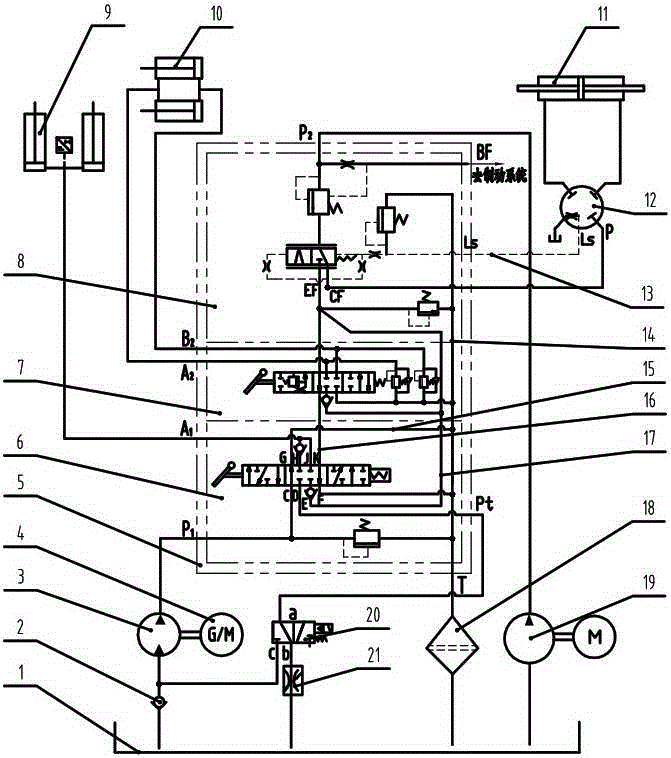
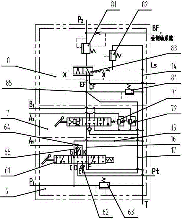
[0022] see figure 1 and figure 2 , a forklift hydraulic system with double-pump oil supply and energy recovery includes a fuel tank 1, a first oil pump 3, a motor 4, a multi-way valve 5, two lifting cylinders 9, two tilting cylinders 10, a steering cylinder 11, and a load sensor Steering gear 12, oil filter 18, second oil pump 19, directional control valve 20, speed limiting valve 21, the components are connected by pipelines; The valve plate 7 and the oil inlet valve plate 8 are composed of a multi-way valve; the oil inlet and return valve plate 6 is provided with a three-position eight-way lifting reversing valve 61 and a first main safety valve 63; the tilting reversing valve The direction valve section 7 includes an inclined three-position six-way reversing valve, a first overload supplement valve 71 and a second overload supplement valve 72; the oil inlet valve section 8 includes a diverter valve 81, a priority valve 83, and a steering safety valve 82 And the second ma...


PUM


Abstract

The invention relates to a forklift hydraulic system with energy recovery and double-pump oil supply functions. The forklift hydraulic system comprises an oil tank, a first oil pump, a motor, a multiway valve, two lifting oil cylinders, two inclined oil cylinders, a steering oil cylinder, a load sensing steering gear, a second oil pump, a directional control valve and a speed limit valve, wherein the multiway valve consists of an oil inlet and return valve plate assembly, an inclined reversing valve plate and an oil inlet valve plate, and is a plate type multiway valve; a three-position eight-way lifting reversing valve and a first main safety valve are arranged in the oil inlet and return valve plate assembly; the inclined reversing valve plate comprises an inclined three-position six-way reversing valve, a first oil adding overload valve and a second oil adding overload valve; the oil inlet valve plate comprises a split-flow valve, a priority valve, a steering safety valve and a second main safety valve. The forklift hydraulic system is suitable for not only hybrid power forklifts but also electric forklifts. For example, after a 7t electric forklift is charged once, according to the test results of an energy consumption test method of the whole vehicle, the energy consumption of the system is reduced by 25%, and the working cycle time of the whole vehicle is prolonged by 50 minutes.

Description

technical field [0001] The invention belongs to the field of hydraulic technology, in particular to a forklift hydraulic system. Background technique [0002] The forklift uses the lifting system to complete the processes of picking up, lifting, stacking, and stacking the goods. When the forklift is picking up goods and descending, it uses various throttling methods to control the descending speed of heavy objects. In this process, the gravitational potential energy is all converted into heat energy through the throttle valve. It will not only cause the temperature rise of the hydraulic system, but also affect the reliability of the system and components and the working efficiency of the whole vehicle. With the increasingly tense international energy supply and the increasing awareness of environmental protection worldwide, green and energy saving have become the future development trend of technologies and products in various industries. The development of the situation ...

Claims


Application Information

Patent Timeline
Patent Type & Authority Patents(China)
IPC IPC(8): B66F9/22
Inventor 温跃清马庆丰陈捷袁正陈仕胜田原余建福
Owner ANHUI HELI CO LTD
Learn More