Magnetofluid-driven straight reciprocating motion structure and application method thereof

A linear reciprocating motion and magnetic fluid technology, applied in the direction of fluid pressure actuators, etc., can solve the problems of large volume, application conditions, large volume of working system, large power consumption, etc., and achieve small volume, simple structure, and wide application in industries Effect

Active Publication Date: 2014-07-30
JINAN YOUBAI ELECTRONICS TECH
View PDF10 Cites 4 Cited by
  • Summary
  • Abstract
  • Description
  • Claims
  • Application Information

AI Technical Summary

Problems solved by technology

[0002] In the fields of industrial control and other fields that are currently on the market, there are many types of products that usually use linear reciprocating motion structures, but there are certain application condition restrictions and large working system defects when using them, for example: using compressed air The cylinder that drives the linear reciprocating motion structure requires compressed air movement and the coordination system of the solenoid valve to work; the hydraulic cylinder that uses hydraulic pressure to drive the linear reciprocating motion structure requires the cooperation of a hydraulic workstation system to work; the electric cylinder that uses the motor to drive the linear reciprocating motion structure , need a set of motor screw drive system with complex structure to work; use electromagnet to drive the traction mechanism of linear reciprocating motion structure, need electromagnet drive with large volume and large power consumption to work, etc.

Method used


Image

  • Magnetofluid-driven straight reciprocating motion structure and application method thereof
  • Magnetofluid-driven straight reciprocating motion structure and application method thereof
  • Magnetofluid-driven straight reciprocating motion structure and application method thereof

Examples


Embodiment Construction

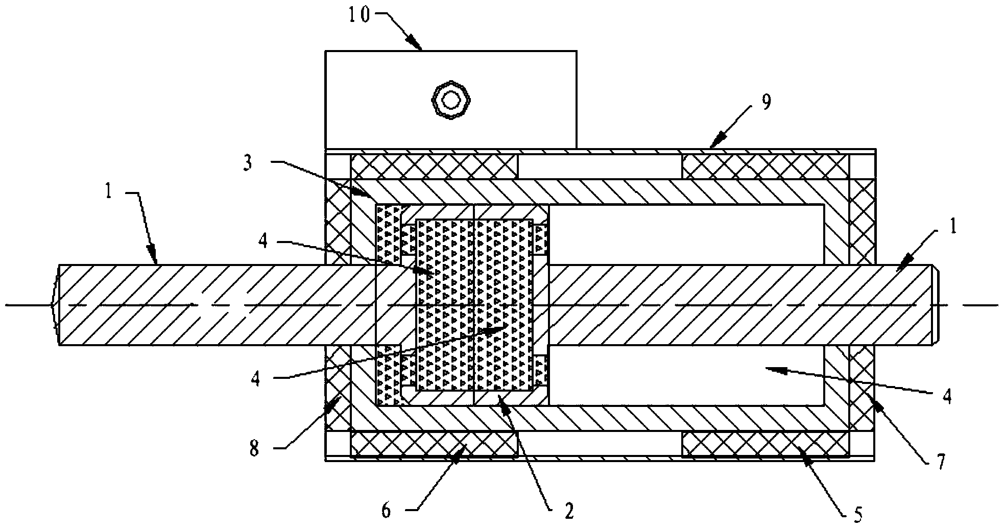
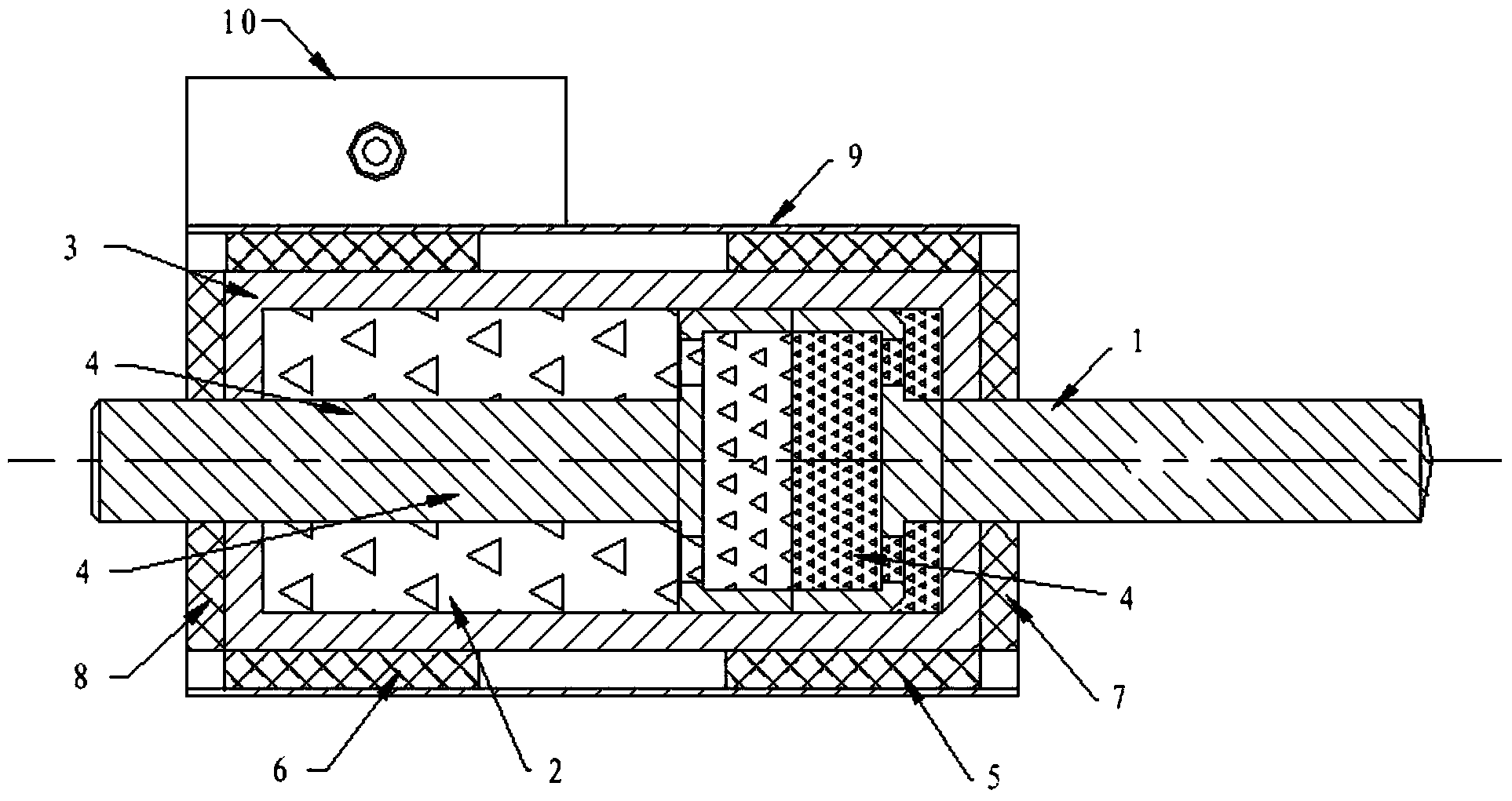
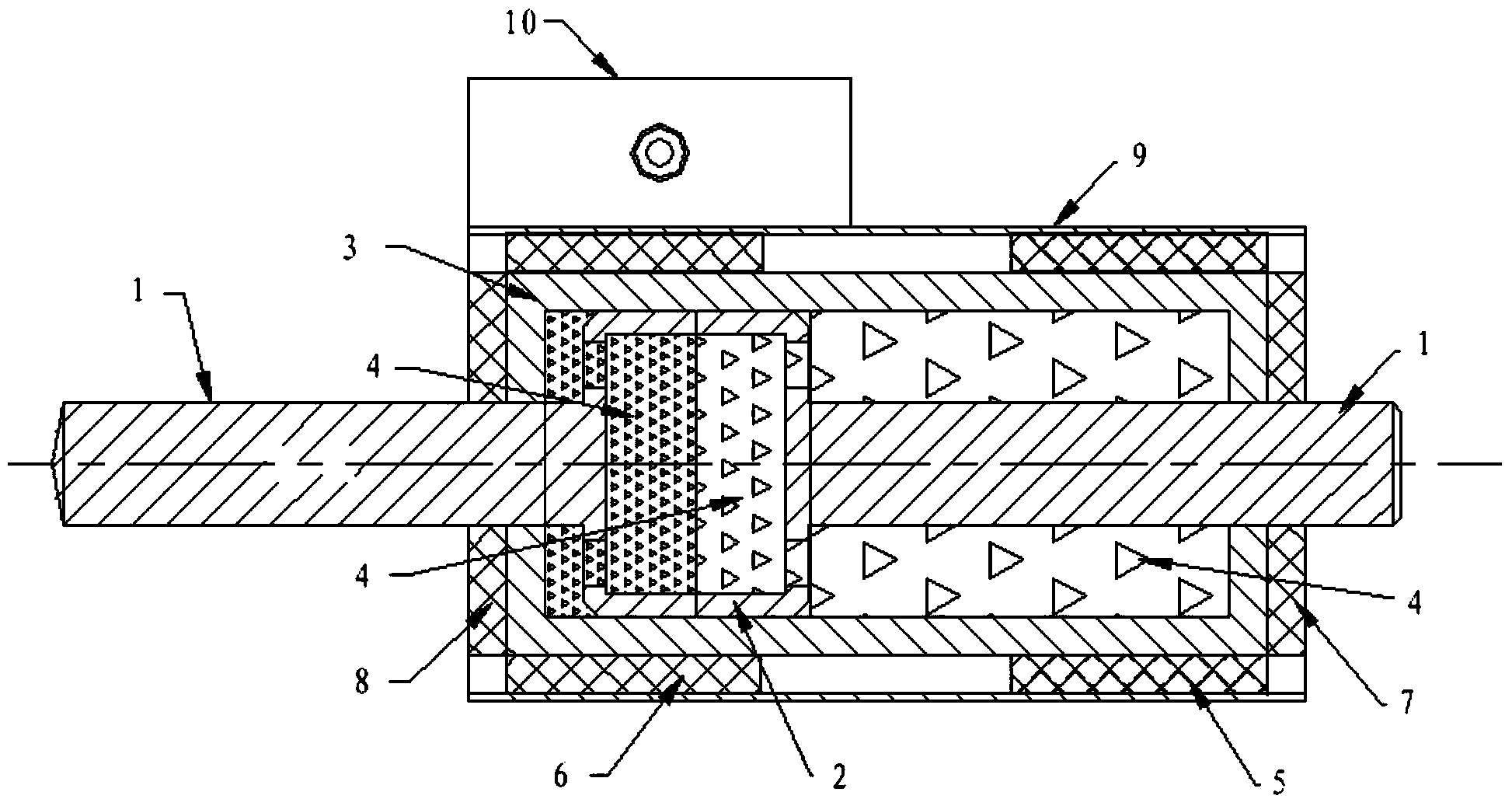
[0035] The present invention will be described in detail below in conjunction with the drawings:

[0036] As we all know, the magnetic fluid commonly used in industry has the following main characteristics:

[0037] 1. It has both the fluidity of liquid and the characteristics of solid magnetic material, and the ability to induce magnetic flux;

[0038] 2. It has the ability to float in the carrier under an external magnetic field;

[0039] 3. Adjusting the intensity of the external magnetic field can change the apparent specific gravity and viscosity of the magnetic fluid, so that the magnetic solid can be stably suspended in it;

[0040] 4. Under the action of the vertical magnetic field, it will spontaneously form a stable peak state;

[0041] 5. The magnetic fluid will flow to and be fixed in the area with high magnetic field strength under the action of an external magnetic field;

[0042] 6. The response speed of the external magnetic field is fast. After the external magnetic field...


PUM


Abstract

The invention discloses a magnetofluid-driven straight reciprocating motion structure and an application method thereof. The magnetofluid-driven straight reciprocating motion structure is characterized by comprising a cylinder body, wherein a dynamic shrinking coil and a dynamic stretching coil are symmetrically arranged on the upper side and the lower side of the cylinder body; a dynamic shrinking planar coil and a dynamic stretching planar coil are symmetrically arranged on the left side and the right side of the cylinder body; a piston is arranged in the cylinder body; the piston is connected with a piston rod; a piston cavity for allowing magnetofluid to be stored and flow is formed in the piston; a drainage hole for allowing the magnetofluid to flow when the magnetofluid is changed in the storage and flowing process is formed in the piston; terminals of the dynamic shrinking coil, the dynamic stretching coil, the dynamic shrinking planar coil and the dynamic stretching planar coil are connected with a power supply and a control switch circuit. The magnetofluid-driven straight reciprocating motion structure and the application method thereof are economic and practical in product manufacturing, simple in operation structure, small in volume of an application system, and energy-saving and low in energy consumption.

Description

Technical field [0001] The invention relates to a linear reciprocating motion structure caused by magnetic fluid and an application method. Background technique [0002] In the industrial control and other fields currently seen in the market, there are usually many types of products that use linear reciprocating motion structures, but there are certain application conditions and limitations in use and the defects of large working systems, such as: using compressed air The cylinder that drives the linear reciprocating motion structure requires compressed air movement and a solenoid valve to work; the hydraulic cylinder that uses the hydraulic drive linear reciprocating motion structure requires a hydraulic workstation system to work; the motor drives the electric cylinder of the linear reciprocating motion structure , A set of motor screw drive system with complex structure is needed to work; the traction mechanism that uses electromagnet to drive linear reciprocating motion struc...

Claims


Application Information

Patent Timeline
Patent Type & Authority Applications(China)
IPC IPC(8): F15B15/14
Inventor 潘宁吴皓马庆
Owner JINAN YOUBAI ELECTRONICS TECH
Why Eureka
Try Eureka