
Curved lever force amplification linear drive punching machine

A linear drive and stamping machine technology, applied in the field of stamping machines, can solve the problems of poor stability in the vertical direction, and achieve the effects of simple structure, improved stability, and obvious force amplification effect

Inactive Publication Date: 2016-10-26
SUZHOU UNIV
View PDF7 Cites 0 Cited by
  • Summary
  • Abstract
  • Description
  • Claims
  • Application Information

AI Technical Summary

Problems solved by technology

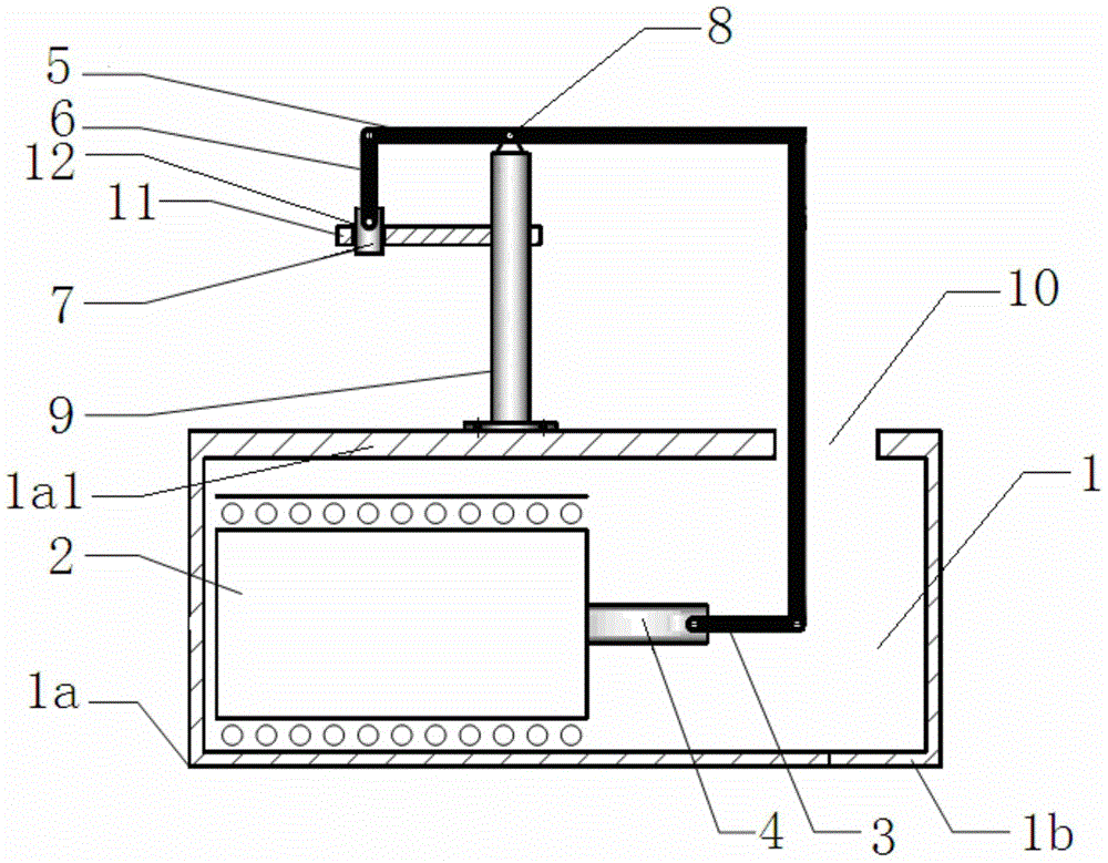
[0007] Preferably, during the entire stamping process, the stamping punch is located between the fulcrum of the curved lever and the driving part, which solves the shortcoming of poor vertical stability in the prior art, thereby further improving the stability of the stamping process sex

Method used


Image

  • Curved lever force amplification linear drive punching machine
  • Curved lever force amplification linear drive punching machine
  • Curved lever force amplification linear drive punching machine

Examples


Embodiment Construction

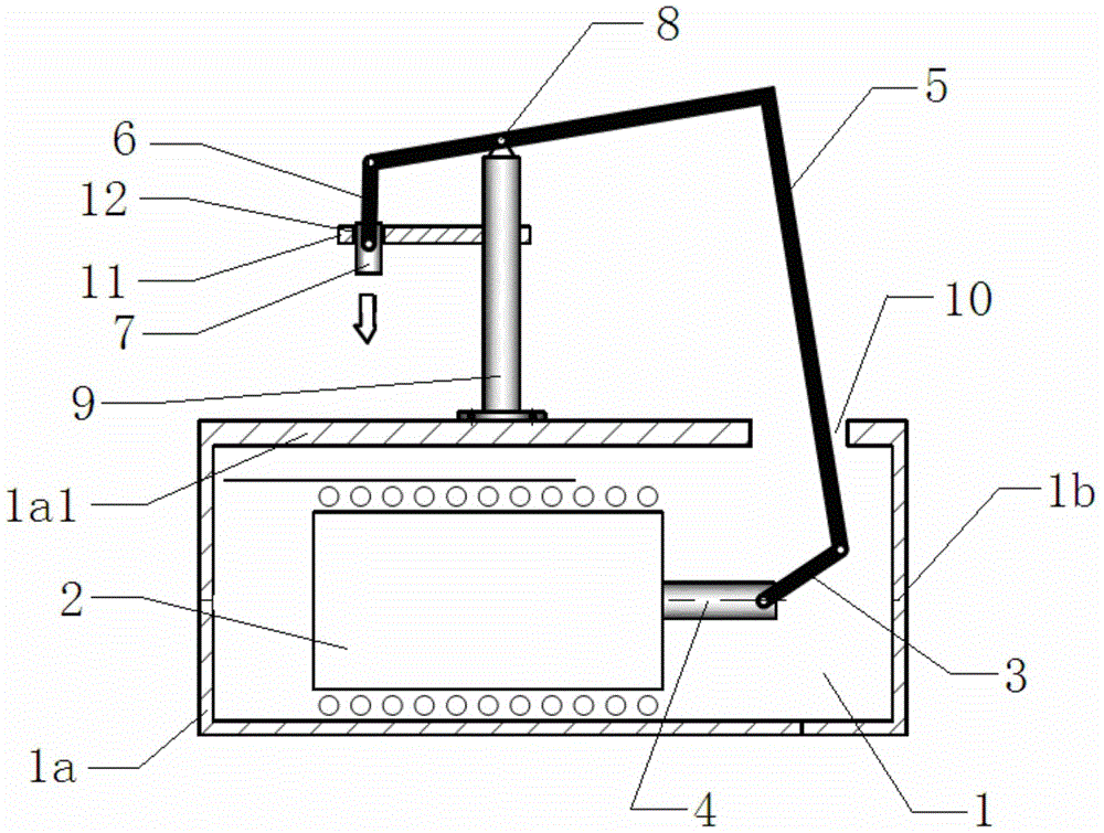
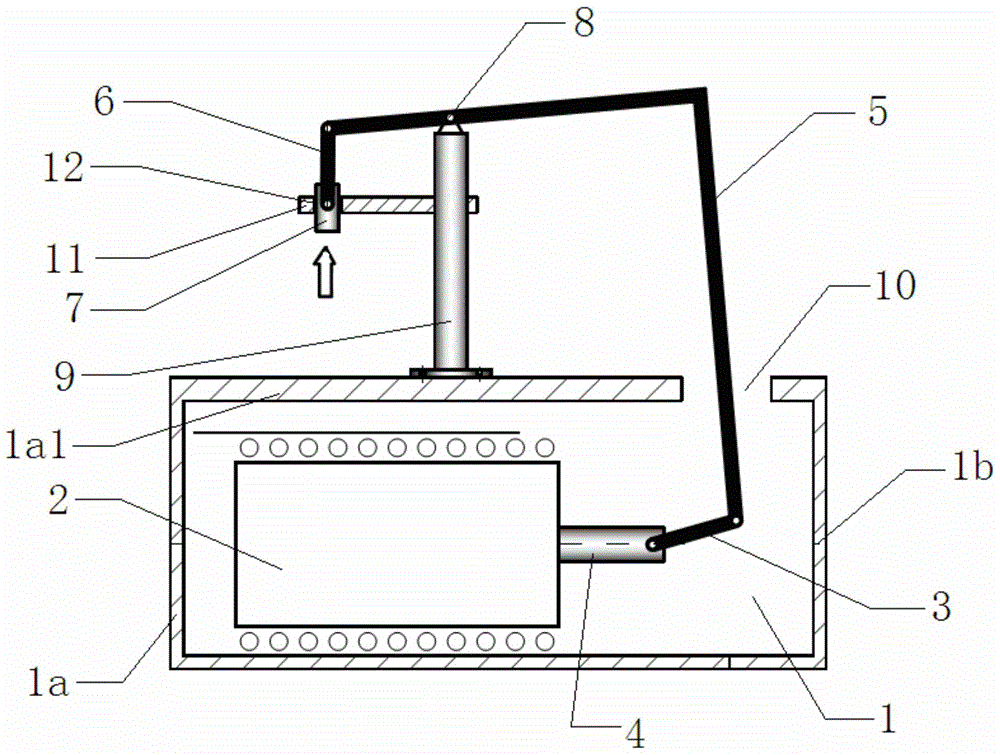
[0027] Example: refer to figure 1 , 2 As shown in , 3, a curved lever force amplifies the linear drive punching machine, including a hollow base 1, a linear motor 2 arranged inside the hollow base 1 and making a linear reciprocating motion along the horizontal direction, one end of which is connected to the linear motor 2 through a hinge 3 The curved lever 5 connected to the output punch 4 at the output end, and the stamping punch 7 connected to the other end of the curved lever 5 through the hinge part 2 6 are provided with a curved lever fulcrum 8 directly above the linear motor 2, and on the upper surface of the hollow base 1 A fulcrum cylinder 9 is provided on the top, and the curved lever fulcrum 8 is located at the top of the fulcrum cylinder 9, and a through hole 10 for the curved lever 5 to swing up and down is provided on the upper surface of the hollow base 1, and at the same time, on the stamping punch 7 side, Below the curved lever fulcrum 8, there is a longitudin...


PUM


Abstract

The invention discloses a bent lever force amplification linear driving punching machine, comprising a hollow base, a driving component, a bent lever and a punching head, wherein the driving component is arranged in the interior of the hollow base and carries out linear reciprocating motion in a horizontal direction, one end of the bent lever is connected with an output punch at the output end of the driving component through an articulation component I, the punching head is connected with the other end of the bent lever through an articulation component II, a bent lever fulcrum is arranged over the driving component, and a through hole for allowing the up-and-down swinging of the bent lever is formed in the upper surface of the hollow base, and meanwhile, a longitudinal guiding mechanism is arranged below the bent lever fulcrum on one side of the punching head and is used for allowing the punching head to carry out linear reciprocating motion in a vertical direction. The bent lever force amplification linear driving punching machine has the advantages that the center of gravity of a machine body in the whole punching process is reduced, so that an operation that the weight of a base needs to be specially increased in order to keep the stability of a machine tool in the prior art is avoided, and the manufacturing cost is saved; the defects of low punching precision and poor stability easily caused by the fact that an upper horizontal rack part is easy to shake left and right in the prior art are overcome.

Description

technical field [0001] The invention relates to a stamping machine, in particular to a crank lever force amplification linear drive stamping machine. Background technique [0002] At present, stamping machines are widely used in stamping and forming of electronics, communications, computers, household appliances, furniture, vehicles, (automobiles, motorcycles, bicycles) hardware parts, etc. At the same time, with the rapid development of the economy and the improvement of people's living standards, More demands are placed on the punching machine. Traditional punching machines mainly include manual punching machines, mechanical punching machines, hydraulic punching machines and pneumatic punching machines. However, manual punching machines have low work efficiency and low pressure, and are suitable for manual processing such as small holes, paper and leather; mechanical Type punching machine, through mechanical transmission, has high speed, high efficiency and large tonnage,...

Claims


Application Information

Patent Timeline
Patent Type & Authority Patents(China)
IPC IPC(8): F16H21/44B21D22/02
CPCB30B1/10
Inventor 王明娣杜秋汤攀飞
Owner SUZHOU UNIV
Learn More