
Multi-mode output circuit testing system capable of carrying out resolving in real time

An output circuit and test system technology, applied in the field of communication, can solve the problems of single mode, poor real-time performance, and low output circuit test accuracy, and achieve the effects of improving real-time performance, low cost, and reducing the amount of manual calculation.

Active Publication Date: 2014-07-30
BEIJING INST OF AEROSPACE CONTROL DEVICES
View PDF3 Cites 13 Cited by
  • Summary
  • Abstract
  • Description
  • Claims
  • Application Information

AI Technical Summary

Problems solved by technology

The upper computer sends test instructions, and the lower computer converts the instructions into control commands to test the functions of the output circuit under test, calculate the test data in real time, provide effective testing methods for the output circuit, and solve the problem of low test accuracy and real-time testing of the output circuit. The problem of poor sex and single mode

Method used


Image

  • Multi-mode output circuit testing system capable of carrying out resolving in real time
  • Multi-mode output circuit testing system capable of carrying out resolving in real time
  • Multi-mode output circuit testing system capable of carrying out resolving in real time

Examples


Embodiment Construction

[0020] The multi-mode output circuit test system that can be solved in real time according to the present invention will be described in further detail below with reference to the accompanying drawings and specific embodiments.

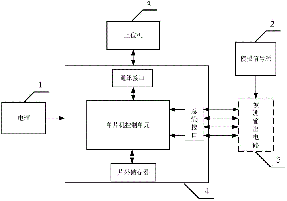
[0021] figure 1 It is a block diagram of a multi-mode output circuit test system that can be solved in real time according to the present invention. like figure 1 As shown, the test system includes a power supply 1 , an analog signal source 2 , an upper computer 3 , and a lower computer 4 . Among them, the power supply 1 provides working power for the lower computer 4 and the output circuit 5 under test. The analog signal source 2 simulates the output of the resolver, and generates sine, cosine and reference signals as input signals of the output circuit 5 under test. The task of the upper computer is to use the test software to send test instructions to the lower computer, and at the same time to receive the test data transmitted by the lower comp...


PUM


Abstract

A multi-mode output circuit testing system capable of carrying out resolving in real time comprises a power source, an analog signal source, an upper computer and a lower computer. The analog signal source is used for simulating output of a rotary transformer, and sine signals, cosine signals and reference signals are generated to be used as input signals of a tested output circuit. The upper computer sends out a testing order to the lower computer, the lower computer generates corresponding control signals according to the order to control a timer counter function and a constant-number timing function of the tested output circuit in real time, a bus interface is used for monitoring fast-rotating protection signals and collecting data of the tested output circuit, the data are processed by the lower computer and then are sent to the upper computer through a communication interface in real time, and the upper computer displays and stores testing results. The system can flexibly send testing orders to the tested output circuit, and collect testing results on the tested output circuit in real time, and system function expandability is enhanced.

Description

technical field [0001] The invention belongs to the field of communication technology, and in particular relates to a multi-mode output circuit test system that can be solved in real time, which is used for functional testing of circuits such as accelerometer measurement output circuits and turntable position measurement output circuits. Background technique [0002] The output circuit used for rotation angle measurement has the advantages of simple structure and high reliability, and is widely used in inertial systems such as various instrument angle tests and turntable position tests. In addition, the output circuit includes a timing counting function module and a constant counting timing function module. [0003] The high precision of the inertial system requires that the output circuit used for rotation angle measurement develops in the direction of high precision, high integration and strong speciality. Taking the gyro accelerometer as an example, the output circuit co...

Claims


Application Information

Patent Timeline
IPC IPC(8): G01R31/28G01C25/00
Inventor 杨志超严小军张沛晗岳辉章丽蕾周敏
Owner BEIJING INST OF AEROSPACE CONTROL DEVICES
Learn More