Beam homogenization method and beam homogenization device

A homogenization and beam technology, applied in the field of optics, can solve problems such as uneven beam intensity distribution, many optical lenses, and light energy loss of frosted glass, so as to improve the homogenization effect and accuracy, expand the coverage area, and avoid complicated debugging Effect

Active Publication Date: 2017-06-16
上海兆九光电技术有限公司
View PDF6 Cites 0 Cited by
  • Summary
  • Abstract
  • Description
  • Claims
  • Application Information

AI Technical Summary

Problems solved by technology

After the LED array is arranged, the light beams emitted by each LED are partially superimposed, resulting in uneven intensity distribution of the light beams, which further leads to a decrease in imaging quality
At present, conventional beam homogenization methods, some use frosted glass to homogenize the beam, but the frosted glass will cause a large loss of light energy, resulting in weakened illumination intensity; some obtain a uniform beam by adjusting the LED arrangement, but The effect is not obvious
The most used homogenization method is to use a fly-eye beam homogenizer to homogenize the beam. However, the structure of the fly-eye beam homogenizer is complex, and more optical lenses are used, which increases the difficulty of debugging and is prone to errors. Affects the uniformity of the beam, and the manufacturing cost and manufacturing difficulty also increase accordingly. Mass production cannot be realized, and the degree of automation is low.
On the other hand, the use of a fly-eye beam homogenizer to homogenize the beam has strict requirements on the placement of the target. The target and the light source need to maintain a specified distance, which has great limitations for targets with uneven surfaces. sex

Method used


Image

  • Beam homogenization method and beam homogenization device
  • Beam homogenization method and beam homogenization device
  • Beam homogenization method and beam homogenization device

Examples


Embodiment 1

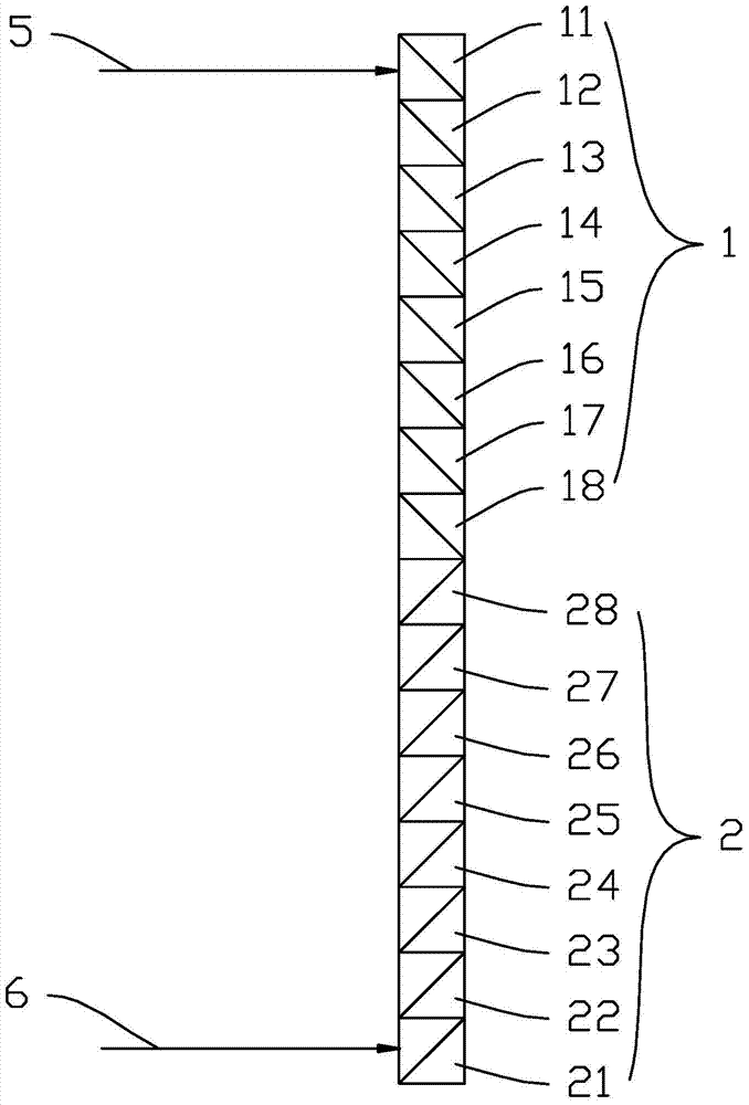
[0033] Such as Figure 1-3 As shown, the beam homogenizing device includes two substrates, which are a first substrate 1 and a second substrate 2 respectively. Wherein, the first substrate 1 and the second substrate 2 are arranged symmetrically on the same vertical plane.

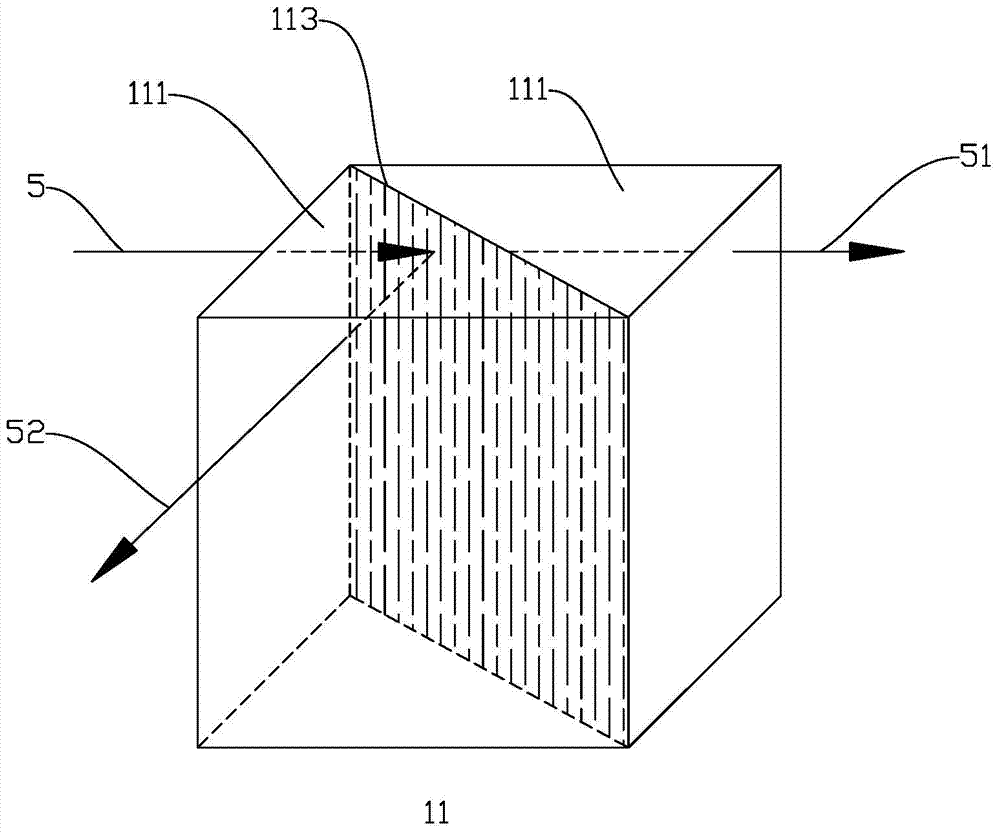
[0034] The first substrate 1 and the second substrate 2 have the same structure. Taking the first substrate 1 as an example, the first substrate 1 includes 8 beam splitters of equal size, from top to bottom are beam splitter 11, beam splitter 12, beam splitter 13, beam splitter 14, beam splitter 15, beam splitter mirror 16, beam splitter 17 and beam splitter 18. Taking the beam splitter 11 as an example, the beam splitter 11 is composed of two isosceles right-angle prisms 111 , and the isosceles right-angle prisms 111 are superimposed on each other so that their oblique surfaces touch each other to form a beam splitting surface 113 . A spectroscopic film (not shown in the figure) is disposed on the spect...

Embodiment 2

[0044] Such as Figure 5 As shown, the beam homogenizing device includes four substrates, namely a first substrate 1 , a second substrate 2 , a third substrate 3 and a fourth substrate 4 . Wherein, the first substrate 1 and the second substrate 2 are arranged symmetrically on the same plane. The third substrate 3 and the fourth substrate 4 are arranged symmetrically on the same plane. The structures of the first substrate 1, the second substrate 2, the third substrate 3 and the fourth substrate 4 are the same.

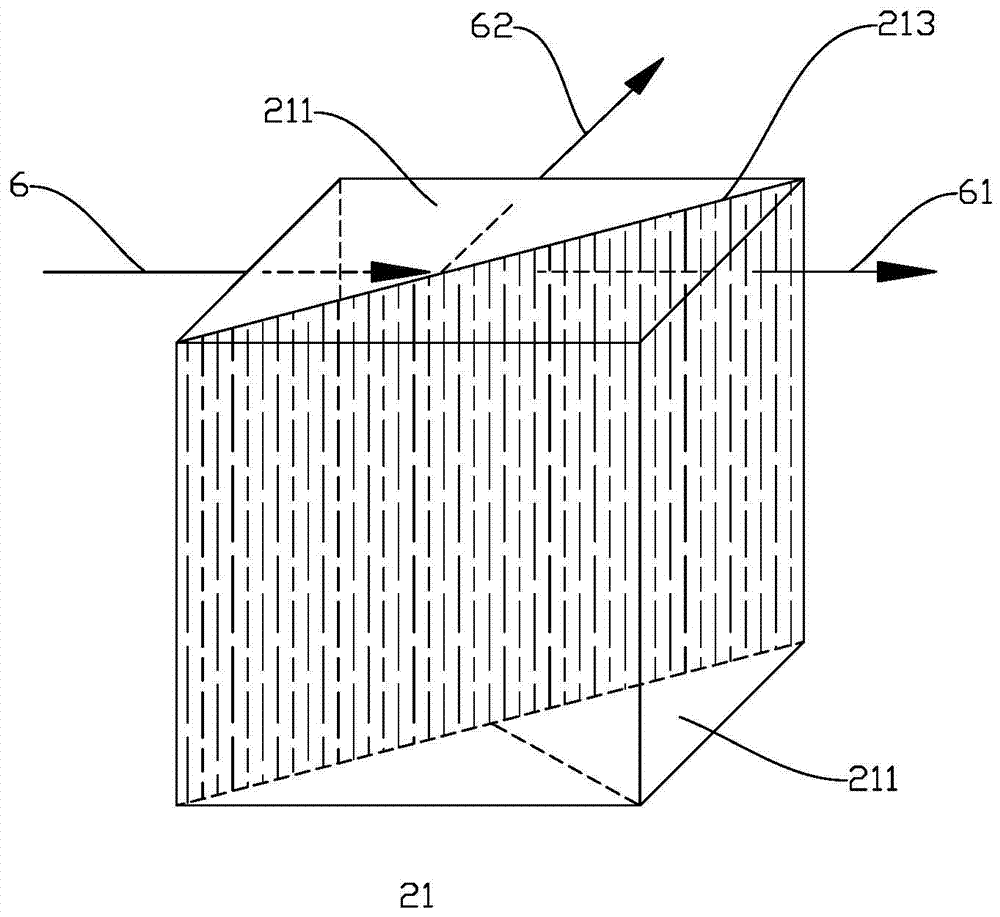
[0045] The third substrate 3 and the fourth substrate 4 are arranged on the propagation path of the first outgoing light beam 7 , and the first outgoing light beam 7 vertically enters the third substrate 3 and the fourth substrate 4 for the second splitting process. The second light beam (not shown in the figure) converted by the third substrate 3 and the second light beam (not shown in the figure) converted by the fourth substrate 4 propagate in opposite directions....


PUM


Abstract

The invention discloses a beam homogenization method, which is characterized in that a plurality of beam-splitting films are arranged on the propagation path of the incident beam, the incident beam transmits through the beam-splitting film to form a first beam, and is reflected by the beam-splitting film to form a second beam; A light beam forms an included angle with a second light beam; the direction of the first light beam is the same as the direction of the incident light beam; and the plurality of light splitting films are arranged along the transmission direction of the second light beam. In the beam homogenizing method provided by the present invention, the incident beam is redistributed by the beam homogenizing device provided with a beam splitting surface, so that it is converted into a uniformly distributed outgoing beam.

Description

technical field [0001] The invention relates to the field of optics, in particular to a beam homogenizing method and a beam homogenizing device. Background technique [0002] With the development of science and technology, people have higher and higher requirements for the intelligence of equipment, and then the machine vision system that uses machines instead of human eyes to make measurements and judgments has emerged as the times require, and is widely used in intelligent transportation, attendance based on face recognition And access control, industrial field intelligent monitoring and detection and other fields. The machine vision system uses a CCD camera to convert the detected target into an image signal, and transmits it to a dedicated image processing system, and converts it into a digital signal according to information such as pixel distribution, brightness, and color, and the image processing system performs various operations on these signals. Extract the chara...

Claims


Application Information

Patent Timeline
Patent Type & Authority Patents(China)
IPC IPC(8): G02B27/10
Inventor 罗新华汤兆胜曾丽金永军孙玉琴
Owner 上海兆九光电技术有限公司
Why Eureka
Try Eureka