
Fly-back electric power converter topological structure and control method thereof

A technology of power converter and topology structure, which is applied in the direction of conversion equipment with intermediate conversion to AC, irreversible DC power input to AC power output, photovoltaic power generation, etc. Problems such as low conversion efficiency, to achieve the effect of reducing voltage and current stress

Inactive Publication Date: 2014-07-30
江苏斯达工业科技有限公司
View PDF8 Cites 10 Cited by
  • Summary
  • Abstract
  • Description
  • Claims
  • Application Information

AI Technical Summary

Problems solved by technology

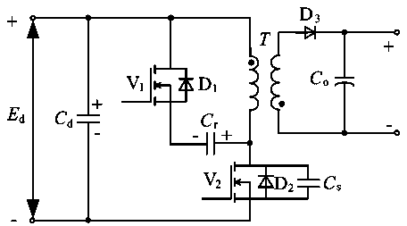
[0003] The topology of the traditional flyback power converter is as follows figure 1 As shown, it can realize the semiconductor switching device V 1 , V 2 The zero-voltage turn-on, but it has the defect of not being able to realize zero-voltage turn-off, and its hard turn-off will cause the turn-off loss of the switching device and the electromagnetic interference caused by the peak voltage during turn-off, and it is different from the V 1 , V 2 Diodes in parallel D 1 、D 2 Also withstand forced conduction and sharply rising reverse voltage shocks
Therefore, the conversion efficiency of the traditional flyback power converter is relatively low, and the voltage and current stress and external electromagnetic interference on the semiconductor device are relatively large.

Method used


Image

  • Fly-back electric power converter topological structure and control method thereof
  • Fly-back electric power converter topological structure and control method thereof
  • Fly-back electric power converter topological structure and control method thereof

Examples


Embodiment Construction

[0018] The following in conjunction with the embodiment figure 2 ~ Fig. 78, further elaborates the specific implementation manner of the present invention, so as to make the technical solution of the present invention easier to understand and grasp.

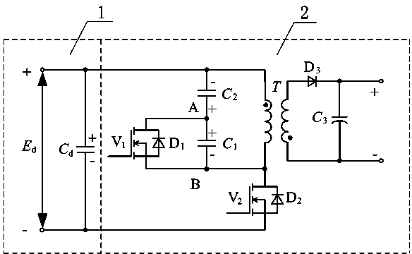
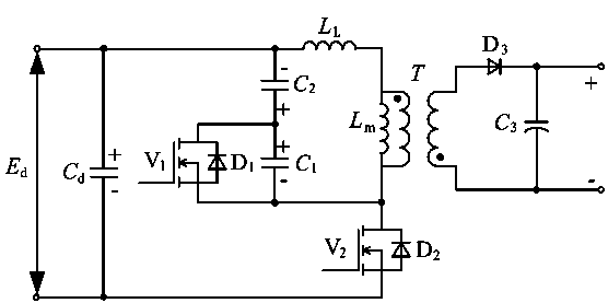
[0019] image 3 yes figure 2 The equivalent circuit, in the figure L L Equivalent to the leakage inductance of the primary winding of the transformer T, L m Equivalent to the excitation inductance of the transformer T, the capacitance C 2 >C 1 . It can be seen from the figure that the hardware topology of a flyback power converter in the present invention includes a DC voltage source E on the input side d , filter and energy storage capacitor C d and flyback converters. Its specific circuit structure is the input side DC power supply E d The positive electrode and the filter energy storage capacitor C d One end of the capacitor C 2 One end of the transformer T is connected to one end of the primary winding; the DC p...


PUM


Abstract

The invention relates to an improved electric power converter topological structure and a control method thereof. The hardware topological structure comprises a direct-current voltage source Ed on the input side, a filtering and energy-storage capacitor Cd and a fly-back converter. The topological structure is characterized in that a capacitor C1 is connected to a proper position of the fly-back converter in parallel, and on-off control of semiconductor switches is conducted on this basis. By the adoption of the topological structure, inherent defects of traditional topological structures can be overcome, it is ensured that zero voltage switching-on and zero voltage switching-off can be achieved for all semiconductor switch devices, natural breakover and natural cutting-off of antiparallel power diodes can be achieved, and voltage and current stress, switching loss and electromagnetic interference on the outside of semiconductor devices are reduced. Thus, the topological structure can improve the conversion efficiency of the converter and the capacity of the converter for restraining the electromagnetic interference. The improved electric power converter topological structure and the control method thereof can be applied to DC-DC conversion as well as DC-AC conversion such as photovoltaic power generation, wind power generation, fuel-cell power generation and communication power supplies.

Description

technical field [0001] The present invention relates to an improved topological structure of a power converter and its control method, in particular to a high-efficiency, low-electromagnetic-interference DC-DC converter or DC-AC converter topology and its control method, which can be used For photovoltaic power generation, wind power generation, fuel cell power generation, and communication power supply, the power generation includes grid-connected power generation and independent power generation. Background technique [0002] In recent years, with the rapid development and utilization of new energy and green environmental protection energy, the performance requirements of power converters by international certification bodies have become more and more stringent, and business competition has become more and more fierce, especially for photovoltaic power generation, wind power generation, In the fields of fuel cell power generation, communication power supply, active power f...

Claims


Application Information

Patent Timeline
IPC IPC(8): H02M3/28H02M1/44H02M7/48
CPCY02E10/56Y02E10/76
Inventor 陈国呈魏仕桂徐亚明蔡立清顾红兵周勤利
Owner 江苏斯达工业科技有限公司
Learn More