Single-sensor double-frequency output resonant circuit and design method thereof

A resonant circuit and inductor technology, applied in induction heating and other directions, can solve the problems of poor frequency selection performance of resonant circuit, complex resonant circuit structure, asynchronous dual-frequency output, etc.

Inactive Publication Date: 2014-07-30
XIAN UNIV OF TECH
View PDF3 Cites 1 Cited by
  • Summary
  • Abstract
  • Description
  • Claims
  • Application Information

AI Technical Summary

Problems solved by technology

[0006] The purpose of the present invention is to provide a single-inductor dual-frequency output resonant circuit, which solves the problems of comp

Method used


Image

  • Single-sensor double-frequency output resonant circuit and design method thereof
  • Single-sensor double-frequency output resonant circuit and design method thereof
  • Single-sensor double-frequency output resonant circuit and design method thereof

Examples


Embodiment 1

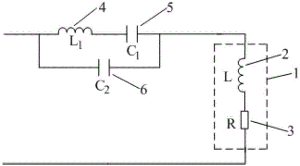
[0102] Embodiment 1, a single-inductor dual-frequency output resonant circuit, including a connected single-inductor 1 and an auxiliary resonant circuit, the single-inductor 1 is composed of an inductor equivalent inductance L2 and an inductor equivalent resistance R3 connected in series; The auxiliary resonant circuit consists of a resonant inductor L 1 4 and the resonant capacitor C 1 5 in series and then with the resonant capacitor C 2 6 are connected in parallel. Its design method is as follows:

[0103] Step 1, determine the resonant circuit topology:

[0104] Resonant inductance L 1 4 and the resonant capacitor C 1 5 in series and then with the resonant capacitor C 2 6 are connected in parallel to form an auxiliary resonant circuit, and the single inductor 1 is connected to the auxiliary resonant circuit to form a resonant circuit.

[0105] Step 2, seek the design parameters of the resonant circuit;

[0106] Select the frequency f of the two signals to be output ...

Embodiment 2

[0116] Embodiment 2, a single-inductor dual-frequency output resonant circuit, including a connected single-inductor and an auxiliary resonant circuit, the single-inductor is composed of an inductor equivalent inductance L and an inductor equivalent resistance R connected in series; the auxiliary resonant The circuit consists of a resonant inductor L 1 and resonant capacitor C 1 connected in series with the resonant capacitor C 2 formed in parallel. Its design method is as follows:

[0117] Step 1, determine the resonant circuit topology:

[0118] Resonant inductance L 1 and resonant capacitor C 1 connected in series with the resonant capacitor C 2 The auxiliary resonant circuit is formed by parallel connection, and the single inductor is connected with the auxiliary resonant circuit to form a resonant circuit.

[0119] Step 2, determining the design parameters of the resonant circuit;

[0120] First select the frequency f of the two signals to be output 1 , f 2 The ...


PUM


Abstract

A single-sensor double-frequency output resonant circuit comprises a single sensor and an auxiliary resonant circuit which are connected, wherein the single sensor is formed by connecting a sensor equivalent inductor L and a sensor equivalent resistor R in series; the auxiliary resonant circuit is formed by connecting a resonant inductor L1 and a resonant capacitor C1 in series and then connecting the resonant inductor L1 and the resonant capacitor C1 with a resonant capacitor C2 in parallel. The designing method of parameters of the single-sensor double-frequency output resonant circuit includes the steps that first, the topological structure of the resonant circuit is determined, and then, according to the impedance characteristics of the resonant circuit, a resonance angular frequency equation of the resonant circuit is built, and the resonant circuit parameters are obtained. The single-sensor double-frequency output resonant circuit is simple in structure, all the parameters are designed totally according to deduction of mathematical logical relations without any additionally-added man-made supposed constraint, no computational items are ignored, the parameters are designed strictly, the circuit resonant frequency determined by the parameters is clear and accurate, the energy utilization rate of a double-frequency output induction heating power source is increased, the selectable frequency range of the double-frequency output resonant circuit is also correspondingly widened, and the double-frequency output performance of the resonant circuit is improved.

Description

technical field [0001] The invention belongs to the technical field of induction heating power supply, and specifically relates to a single-inductor dual-frequency output resonant circuit; the invention also relates to a design method of the resonant circuit. Background technique [0002] The induction heating device is a device that uses the principle of electromagnetic induction to convert electrical energy into heat energy. In the application of induction heating, the induction coil is not in direct contact with the workpiece to be heated, and the alternating current in the coil generates an alternating magnetic field of the same frequency. An induced current (eddy current) is generated inside the heated workpiece to heat the workpiece. Existing studies have shown that the frequency of the current in the induction coil is an important factor in determining the heating performance of the workpiece. Since the current frequency is inversely proportional to the heating thick...

Claims


Application Information

Patent Timeline
IPC IPC(8): H05B6/02
Inventor 冷朝霞刘庆丰田地尚麦霞
Owner XIAN UNIV OF TECH
Why Eureka
Try Eureka