A single-inductor dual-frequency output resonant circuit and its design method
A resonant circuit and inductor technology, applied in the design of resonant circuits, in the field of single-inductor dual-frequency output resonant circuits, can solve the problems of complex resonant circuit structure, poor frequency selection performance of resonant circuits, asynchronous dual-frequency output, etc.
- Summary
- Abstract
- Description
- Claims
- Application Information
AI Technical Summary
Problems solved by technology
Method used
Image
Examples
Embodiment 1
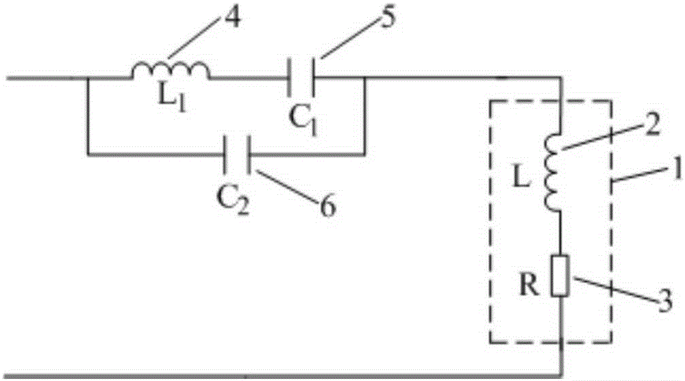
[0102] Embodiment 1, a single-inductor dual-frequency output resonant circuit, including a connected single-inductor 1 and an auxiliary resonant circuit, the single-inductor 1 is formed by the inductor equivalent inductance L2 and the inductor equivalent resistance R3 in series with each other; The auxiliary resonance circuit consists of the resonance inductance L 1 4 and resonant capacitor C 1 5 after series connection with resonant capacitor C 2 6 are connected in parallel. The design method is as follows:
[0103] Step 1. Determine the topological structure of the resonance circuit:
[0104] Resonance inductance L 1 4 and resonant capacitor C 1 5 after series connection with resonant capacitor C 2 6 is connected in parallel to form an auxiliary resonance circuit, and the single inductor 1 is connected with the auxiliary resonance circuit to form a resonance circuit.
[0105] Step 2. Find the design parameters of the resonance circuit;
[0106] Select the frequency f of the two sig...
Embodiment 2
[0116] Embodiment 2, a single-inductor dual-frequency output resonant circuit, including a connected single-inductor and an auxiliary resonant circuit, the single-inductor is formed by the inductor equivalent inductance L and the inductor equivalent resistance R in series; auxiliary resonance The circuit consists of resonant inductor L 1 And resonant capacitor C 1 After connecting in series with the resonant capacitor C 2 Connected in parallel. The design method is as follows:
[0117] Step 1. Determine the topological structure of the resonance circuit:
[0118] Resonance inductance L 1 And resonant capacitor C 1 After connecting in series with the resonant capacitor C 2 The auxiliary resonance circuit is formed in parallel, and the single inductor is connected with the auxiliary resonance circuit to form a resonance circuit.
[0119] Step 2. Determine the design parameters of the resonance circuit;
[0120] First select the frequency f of the two signals to be output 1 , F 2 The hi...
PUM
 Abstract
Description
Claims
Application Information
 - R&D
- Intellectual Property
- Life Sciences
- Materials
- Tech Scout
- Unparalleled Data Quality
- Higher Quality Content
- 60% Fewer Hallucinations
Browse by: Latest US Patents, China's latest patents, Technical Efficacy Thesaurus, Application Domain, Technology Topic, Popular Technical Reports.
© 2025 PatSnap. All rights reserved.Legal|Privacy policy|Modern Slavery Act Transparency Statement|Sitemap|About US| Contact US: help@patsnap.com


