Method for reshaping a turbomachine blade that has at least one zone that has become deformed using peening

An area and blade technology, applied in the maintenance field of any turbine engine blade, can solve problems such as difficult implementation, no repair of IBR, etc., and achieve the effect of restoring shape

Active Publication Date: 2014-07-30
SN DETUDE & DE CONSTR DE MOTEURS DAVIATION S N E C M A
View PDF13 Cites 5 Cited by
  • Summary
  • Abstract
  • Description
  • Claims
  • Application Information

AI Technical Summary

Problems solved by technology

This method is appropriate when part of the blade has been torn, but is difficult to implement when the

Method used


Image

  • Method for reshaping a turbomachine blade that has at least one zone that has become deformed using peening
  • Method for reshaping a turbomachine blade that has at least one zone that has become deformed using peening

Examples


Embodiment Construction

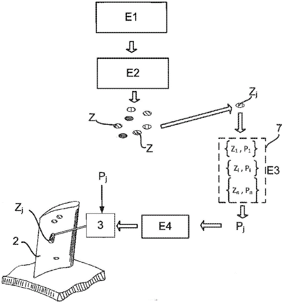
[0038] It should be noted that the accompanying drawings disclose the invention in a detailed manner to carry it out, which drawings can of course be used to give a better definition of the invention where appropriate.

[0039] The invention represents the reshaping of turbine engine blades belonging to an integral blade rotor (IBR) of a turbojet engine, but the following description applies of course to any turbine engine blade.

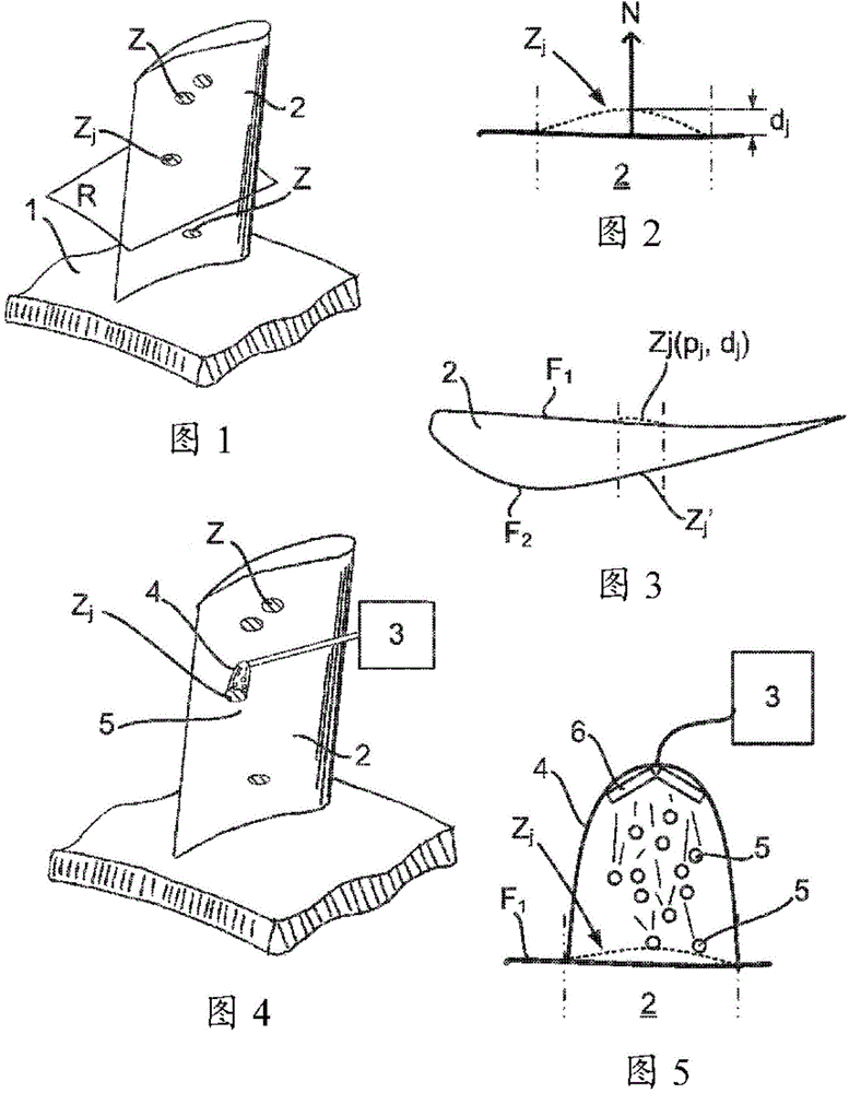
[0040] figure 1 Shown is a part IBR of an axial turbojet with an axially extending annular rim 1 and radially extending vanes 2 . For clarity, figure 1 Only blade 2 of the IBR is shown. During the operation of the aircraft, the blades 2 of the IBR deform, which affects their aerodynamic performance. In order to detect the deformation of the blade 2 to be reshaped, several manual or automatic methods are possible.

[0041] Such as figure 1 As shown in , the blade 2 to be reshaped comprises several deformation zones Z that impair the aerodynamic ...


PUM


Abstract

Method for reshaping a turbomachine blade (2) comprising at least one deformed zone (Z), the method involving acquisition of a profile of said blade, comparing said profile against a reference profile in order therefrom to deduce at least one deformed zone (Zj) of the blade (2), comparing the deformed zone (Zj) against a deformation database (7) containing a plurality of deformed zones (Zj) each respectively associated with a plurality of settings (Pj) for a peening device (3), determining the setting (Pj) associated with said deformed zone (Zj) and peening the deformed zone (Zj) of the blade (2) using the peening device (3) on the basis of said determined setting (Pj) so as to restore said zone (Z) to the proper shape.

Description

technical field [0001] The present invention relates to the field of repair of integrally bladed rotors (IBR) of aircraft turbojet engines, and more particularly to the repair of any turbine engine blades. Background technique [0002] Aircraft jet engines generally comprise a multi-bladed rotor disk mounted axially in the turbojet. The upstream bladed disks known to those skilled in the art as fans have the function of accelerating the airflow from upstream to downstream in a turbojet engine on the one hand and providing the thrust of the aircraft on the other hand. [0003] When the aircraft is in flight, the turbojet engine may ingest foreign objects (birds, dust, etc.) that damage and deform the fan blades. This then reduces the performance level and service life of the fan blades, which represents a drawback. In a known manner, to reshape a fan blade, the latter is placed in a die with a cavity whose shape corresponds to that of the optimally shaped blade. Once said ...

Claims


Application Information

Patent Timeline
IPC IPC(8): B23P6/00F01D5/00F01D5/34B24C1/04B24C5/00C21D7/00B24B1/04B24B39/00B24C1/10
CPCB23P6/002B23P9/04B24B1/04B24B39/00B24C1/04B24C1/10B24C5/005F01D5/005F01D5/34C21D7/06C21D7/00F05D2230/90Y02T50/60Y10T29/49336B23P6/00F01D5/286B21D31/06B23P2700/01
Inventor 杰拉德·德瑞恩
Owner SN DETUDE & DE CONSTR DE MOTEURS DAVIATION S N E C M A
Why Eureka
Try Eureka