Dust sweeping device for filter element of dust collector

A dust collector and ash sweeping technology, applied in the fields of dispersed particle filtration, chemical instruments and methods, dispersed particle separation, etc. The effect of high work efficiency and long service life

Active Publication Date: 2016-06-01
HENAN DRAGON INTO COAL TECH CO LTD
View PDF7 Cites 0 Cited by
  • Summary
  • Abstract
  • Description
  • Claims
  • Application Information

AI Technical Summary

Problems solved by technology

[0003] More suitable for high-temperature dust removal is the dust collector with tubular filter element structure. A large amount of particle dust, as the dust continues to increase, will affect the filtration quality, so it is necessary to remove the dust accumulated on the surface of the filter element. Now the blowing pipe is commonly used, and the pulse blowing method is used to achieve reverse cleaning, but the back blowing The result is that the purified air must re-enter the pre-purified space. Since the amount of purified gas used for each injection is relatively large, the second filtration can only be re-purified, which is not conducive to improving work efficiency, and it is necessary to increase the gas boosting equipment. Yes, because the tubular nozzle can only clean the filter element corresponding to the nozzle, the nozzle cannot change the direction of blowback, and there are dead corners during the nozzle that are not easy to clean, and the accumulation of unfavorable nozzles will become more solid and difficult to remove, so it cannot be easily removed. Good and thorough dust removal; CN101314092A discloses an environmental protection device for controlling particulate matter and gas pollutants in industrial and domestic waste gas, which uses rotating parts to actively meet particulate matter and gas pollutants in exhaust gas, which simplifies the equipment and reduces However, its dust removal effect is average. When it is applied in the coal high-efficiency field, its poor filtering effect will affect the next process, and the use of motor drive will inevitably increase the cost investment; some manufacturers design to use mechanical dust removal Devices, such as installing brushes at the front of the manipulator, or mechanical oscillation methods, are not only complex in structure, but also easily damage the filter element of the dust collector. After the filter element is damaged, production must be stopped to replace the filter element, and dust entering the clean air chamber of the dust collector will pollute the purification The gas is brought into the follow-up process to cause great loss. In addition, the number of filter elements is large and the cleaning efficiency is low. It is difficult to clean the filter elements quickly.

Method used


Image

  • Dust sweeping device for filter element of dust collector
  • Dust sweeping device for filter element of dust collector
  • Dust sweeping device for filter element of dust collector

Examples


Embodiment 1

[0024] Such as figure 1 , figure 2 , image 3 with Figure 4 As shown, a dust-sweeping device for a filter element of a dust collector includes a rotating bracket and a rotating dust-sweeping mechanism.

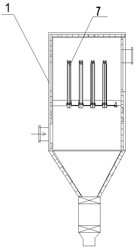
[0025] The rotating bracket is divided into upper and lower parts, the lower part of the rotating bracket is arranged at the opening of the filter element 7 of the dust collector, and the upper part of the rotating bracket is arranged at the top of the filter element 7 of the dust collector.

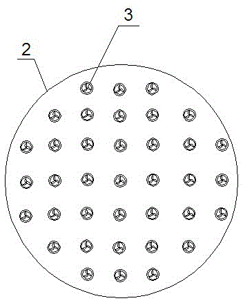
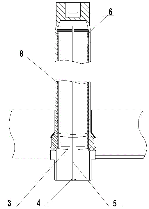
[0026] The rotating ash sweeping mechanism includes fan blades 3, a main shaft 5 and a dust sweeping mechanism, the main shaft 5 runs through the fan blades 3 and the ash sweeping mechanism, and the main shaft 5 is connected with a rotating bracket.

[0027] The dust sweeping mechanism includes a rectangular frame 6 and bristles 8 , and the bristles 8 are arranged outside the rectangular frame 6 .

[0028] The main shaft 5 is connected with the rotating bracket through the bearing...

specific Embodiment 2

[0030] The difference from the first embodiment is that the number of the fan blades 3 is two or three.

[0031] Working principle and structure of the present invention are described in conjunction with embodiment and technical scheme:

[0032]In the present invention, the gas that needs to be filtered enters the cavity through the air inlet hole at the lower part of the dust collector 1, and is continuously discharged to the upper outlet under the drive of the air flow. A partition is set in the middle of the dust collector to play a sealing role to isolate static air. and unfiltered gas, set the dust collector filter element on the partition to filter the gas; after long-term use, the surface of the dust collector filter element in contact with the unfiltered gas has accumulated a large amount of dust, which seriously affects the filtration efficiency and needs to be dealt with in time , so as to ensure the normal passage of gas; the present invention is designed according ...


PUM


Abstract

The invention discloses a dust sweeping device for a dust catcher filter element. The device comprises a rotary bracket and a rotary dust sweeping mechanism, wherein the dust sweeping mechanism is arranged on the rotary bracket; the rotary bracket is arranged at the bottom of the dust catcher filter element; the rotary bracket is divided into an upper part and a lower part; the lower part of the rotary bracket is arranged at the opening of the dust catcher filter element; the upper part of the rotary bracket is arranged at the bottom of the dust catcher filter element; the rotary dust sweeping mechanism comprises a fan blade, a main shaft and a dust sweeping module; the main shaft penetrates through the fan blade and the dust sweeping module; the main shaft is connected with the rotary bracket. The device has the advantages that the fan blade is pushed to rotate through airflow, the fan blade rotates to drive the main shaft so as to ensure that a brush performs rotary motion in the filter element, dust is thoroughly removed, the cleaning effect is very high, the mechanism is simple, the brush can continuously perform sweeping without power, the device is convenient and efficient, the filter element is protected, the service life of the filter element is prolonged, the running benefit of a dust catcher is improved, and the device is applicable to promotion and application.

Description

technical field [0001] The invention belongs to the technical field of dust removal equipment for filter cores of dust collectors, and in particular relates to a dust sweeping device for filter cores of dust collectors. Background technique [0002] our country oil , Natural gas resources are scarce, and coal will remain the most important primary energy source in my country for a long time to come; however, there are many problems and challenges in the process of coal conversion and utilization, such as low comprehensive utilization efficiency, serious environmental pollution, water shortage and carbon dioxide emissions Therefore, it is an inevitable choice for the development of my country's energy industry to develop efficient and clean comprehensive utilization technologies for coal to achieve energy conservation and emission reduction; and the "Twelfth Five-Year Plan for the Development of Clean Coal Technology" that the state encourages development includes "coal Qualit...

Claims


Application Information

Patent Timeline
Patent Type & Authority Patents(China)
IPC IPC(8): B01D46/00
Inventor 朱书成赵家亮李金峰庞志峰
Owner HENAN DRAGON INTO COAL TECH CO LTD
Why Eureka
Try Eureka