Welding apparatus

A welding device and welding process technology, applied in welding monitoring device, welding power source, welding power source and other directions, can solve the problems of inability to realize welding and deviation of oxide film damage phenomenon.

Active Publication Date: 2014-08-06
NIPPON AVIONICS CO LTD
View PDF8 Cites 7 Cited by
  • Summary
  • Abstract
  • Description
  • Claims
  • Application Information

AI Technical Summary

Problems solved by technology

However, the destruction phenomenon of the oxide film varies, and the conventional control method of making the current conduction time of the counter electrode constant cannot cope with this variation, and proper welding cannot be realized.
[0012] In addition, the above-mentioned problems are not limited to laminated lithium-ion batteries, but also occur when a plurality of Al foils or Cu foils are joined together.

Method used


Image

  • Welding apparatus
  • Welding apparatus
  • Welding apparatus

Examples


no. 1 Embodiment

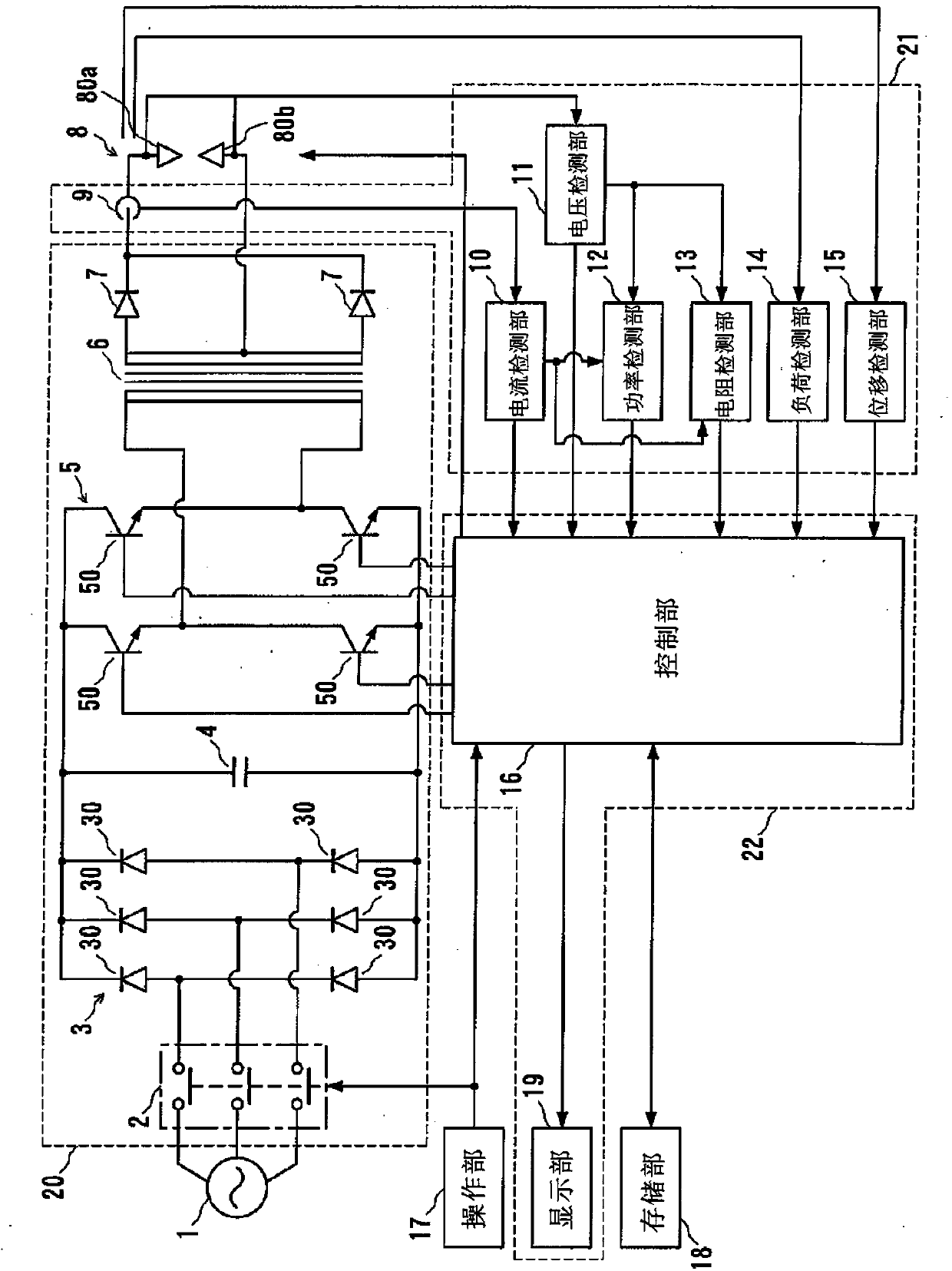
[0026] Hereinafter, embodiments of the present invention will be described with reference to the drawings. figure 1 It is a block diagram showing the configuration of the welding device according to the first embodiment of the present invention. The welding device of this embodiment includes a start switch 2, a rectifier circuit 3, a capacitor 4, a converter 5, a welding transformer 6, a diode 7, a welding head 8, a Hall element 9, a current detection part 10, a voltage detection part 11, a power detection part 12 , resistance detection part 13 , load detection part 14 , displacement detection part 15 , control part 16 , operation part 17 , storage part 18 and display part 19 .

[0027] A start switch 2 , a rectifier circuit 3 , a capacitor 4 , an inverter 5 , a welding transformer 6 , and a diode 7 constitute a welding power source 20 that supplies current to a welding head 8 . In addition, the Hall element 9, the current detection unit 10, the voltage detection unit 11, th...

no. 2 Embodiment

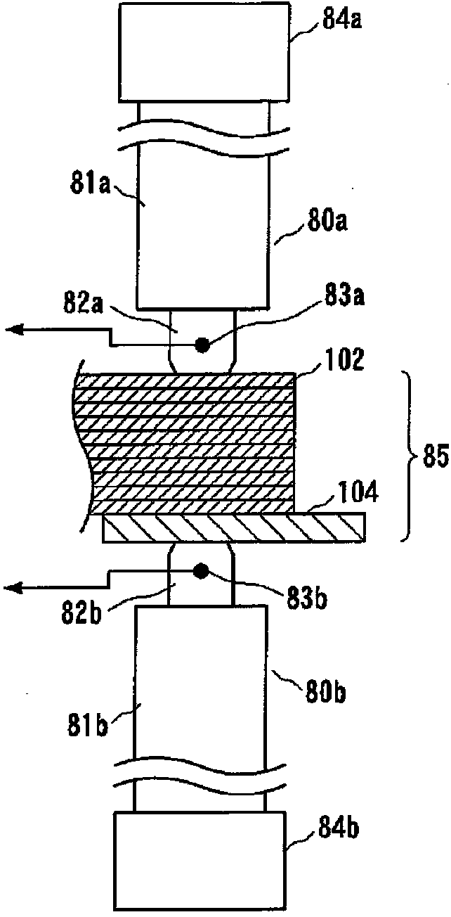
[0044] Next, a second embodiment of the present invention will be described. This embodiment describes an example of more specific control. In this embodiment, the structure of the welding device is the same as that of the first embodiment, so use Figure 1 to Figure 5 The reference signs are used for explanation. Figure 6 It is a flowchart showing the operation of the welding device of this embodiment. In addition, below, the electrodes 80a, 80b will be applied such as image 3 The case of 1 pulse current shown is counted as 1 time.

[0045] First, when the user instructs to start welding, the control unit 16 uses the inter-electrode resistance value R previously set in the storage unit 18 0 Welding with the resistance control method as the end condition value ( Figure 6 step S1). The welding method in the resistance control mode is as described in the first embodiment. At this time, the control unit 16 performs welding in the resistance control mode n times (n is an...

no. 3 Embodiment

[0052]Next, a third embodiment of the present invention will be described. In this embodiment, by changing the structure of the object to be bonded in the first embodiment and the second embodiment, in addition to the effects described in the first embodiment and the second embodiment, the electrode consumption can be suppressed. In this embodiment, the structure of the welding device is also the same as that of the first embodiment and the second embodiment, so use figure 1 , Figure 3 ~ Figure 6 The reference signs are described.

[0053] As described above, in resistance welding, it is possible to suppress generation of metal powder and breakage of tabs, which are problems in ultrasonic welding and laser welding. However, the material to be joined made of Al or Cu has low electrical resistance and does not generate heat easily. Therefore, when a plurality of tabs are to be joined, it is necessary to flow a large current through the electrodes, and there is a problem that...


PUM


Abstract

The invention provides a welding apparatus, comprising electrodes (80a,80b) abutted against a to-be-welded object, a welding power source (20), a detection unit (21) for detecting physical quantities related to the to-be-welded object in welding, and a control unit (16). The control unit supplies current to the electrodes (80a,80b) from the welding power source (20) according to indications from an external part, and thus welding is started, current supplied to the electrodes (80a,80b) is cut off when the detected physical quantities reach predetermined ending condition values in the welding process. The physical quantities is at least one of welding current, welding voltage, welding power, resistance between the electrodes, load applied to the to-be-welded object, and displacement of the to-be-welded object in a thickness direction.

Description

technical field [0001] The present invention relates to a welding device, and particularly relates to a welding device suitable for joining a laminated body of a plurality of plates. Background technique [0002] In recent years, a stacked lithium ion battery in which a plurality of flat positive electrodes and negative electrodes are stacked with a separator interposed therebetween has been used. Figure 9A It is a perspective view showing the stacked state of the stacked lithium ion battery, Figure 9B It is a perspective view showing a state where tabs of electrodes and lead terminals are connected. [0003] In stacked lithium-ion batteries, such as Figure 9A As shown, positive electrodes 100 made of metal foils such as aluminum (Al) and negative electrodes 101 made of metal foils such as copper (Cu) are alternately laminated with separators (not shown) interposed therebetween. A tab 102 for wire bonding is provided on each positive electrode 100 . These tabs 102 are a...

Claims


Application Information

Patent Timeline
Patent Type & Authority Applications(China)
IPC IPC(8): B23K11/00B23K11/24B23K11/25B23K11/02
CPCB23K11/00B23K11/02B23K11/241B23K11/25
Inventor 伊藤厚重松孝英
Owner NIPPON AVIONICS CO LTD
Why Eureka
Try Eureka