Manufacturing process of particle collecting structure

A particle capture and manufacturing process technology, applied in the field of particle traps, can solve the problems of high processing cost, difficult processing, lack of structural processing devices, etc.

Inactive Publication Date: 2014-08-06
ZHEJIANG TIANZE ENVIRONMENTAL TECH
View PDF6 Cites 1 Cited by
  • Summary
  • Abstract
  • Description
  • Claims
  • Application Information

AI Technical Summary

Problems solved by technology

However, this solution lacks a processing device with a reaso

Method used


Image

  • Manufacturing process of particle collecting structure
  • Manufacturing process of particle collecting structure
  • Manufacturing process of particle collecting structure

Examples


Embodiment 1

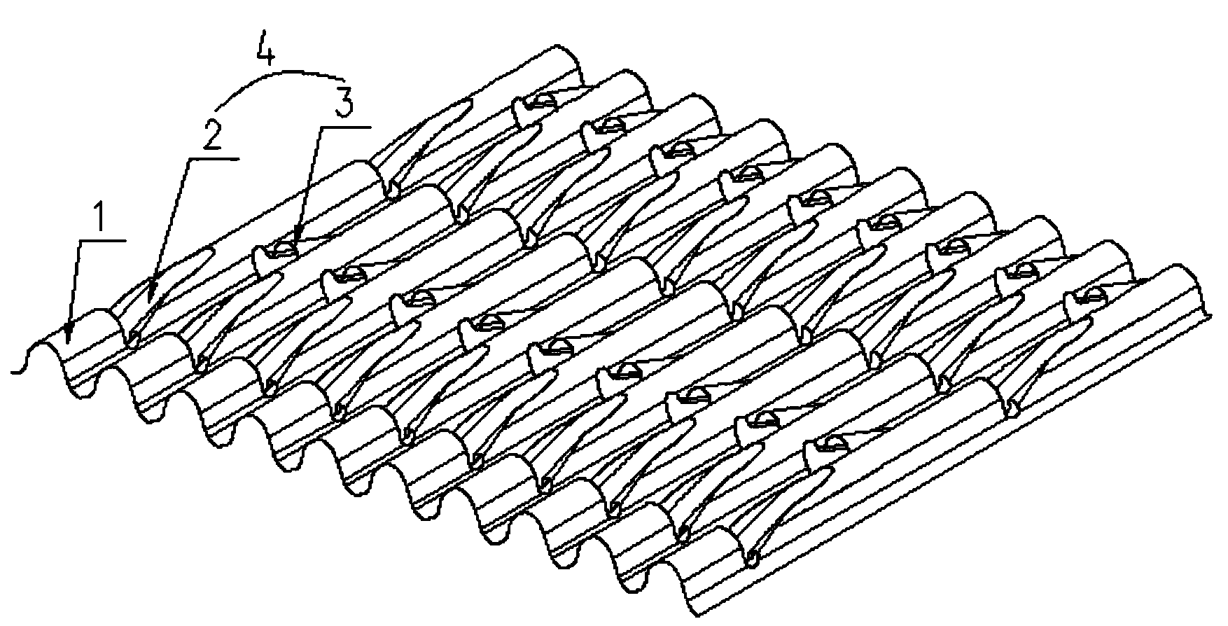
[0029] refer to figure 1 , figure 2 , image 3 As shown, a particle trapping structure, the body of which is a wave plate 1 with a corrugated cross-section, and a plurality of blocking structures 4 are evenly arranged on the longitudinal crests and troughs, and are integrally formed on the wave plate 1, Its production process includes:

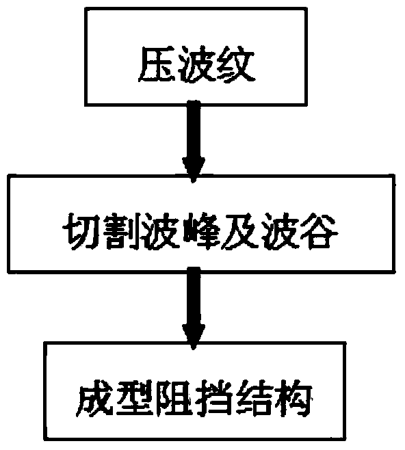
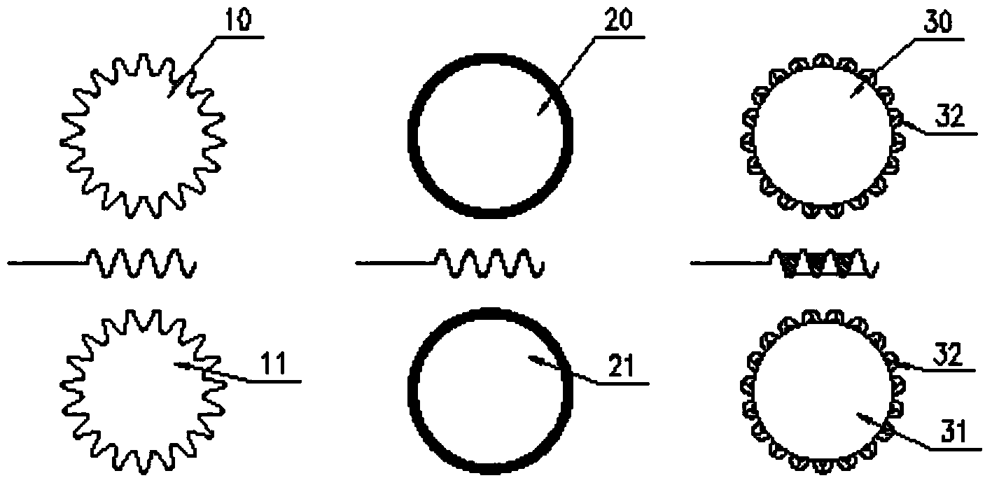
[0030] a) Corrugation: roll the metal flat plate into a corrugated plate by rolling the pressure pulsator 10, 11 up and down;

[0031] b) Cutting wave crests and troughs: use the upper circular blade 20 to roll and cut the wave crests of the wave board to form gaps, and at the same time, use the lower circular blade 21 to roll and cut the wave troughs to form gaps, and the gaps on the wave peaks and wave troughs are evenly staggered vertically;

[0032] c) Forming the blocking structure: the wave board that has completed step b is formed into the blocking structure 4 by rolling the arc pressure heads 30 and 31 up and down in a unified dire...

Embodiment 2

[0035] refer to Figure 4 As shown, by merging the tooling in step a and step b in embodiment 1, the upper and lower circular blades 20, 21 in step b are correspondingly installed on the tooling in step a, and the upper and lower rolling pressure pulsators 10, 11 Up, refit into rolling pressure pulsators 12 and 13 with upper and lower circular blades, and then roll the metal flat plate to form a wave plate with gaps, and finally follow step c in Example 1 to form particles capture structure.

[0036] Through the combination of tooling, one process can be saved in the manufacturing process of the particle trapping structure, and the processing cost can be reduced at the same time.

Embodiment 3

[0038] refer to Figure 5 As shown, by merging the tooling in step a, step b and step c in embodiment 1, the circular blade in step b is correspondingly installed on the tooling in step a, on the rolling pressure pulsator 10, 11, and then The arc pressure head 32 of step c is uniformly installed on the groove of the upper and lower rolling pressure pulsators and one side of the circular blade, and is refitted as the upper and next forming pressure pulsators 14, 15, and then the metal plate is rolled. The particle trapping structure can be molded at one time.

[0039] Through the combination of tooling, the particle trapping structure is formed at one time, the process is simple, the operation is convenient, and the processing cost is greatly reduced.


PUM


Abstract

The invention discloses a particle collecting structure, and relates to the technical field of particle collecting devices. A body of the particle collecting structure is a waved plate with a wavy cross section, and a plurality of blocking structures are evenly arranged on the longitudinal wave crest and wave trough of the waved plate in a staggered mode, and are integrally formed on the waved plate. A manufacturing process of the particle collecting structure comprises the steps that (a) ripples are pressed, and a flat metal plate is molded into the waved plate; (b) the wave crest and the wave trough are cut, and clearances are longitudinally and evenly cut in the wave crest and the wave trough of the waved plate in a staggered mode; (c) the blocking structures are formed, and the blocking structures are formed on the wave crest or the wave trough of the wavy plate with the step b completed on one side of the unified direction of the clearances. The three procedures can be carried out at the same time and can be completed step by step in a combined mode, a continuous rolling mode or a sectional type punching mode can be adopted as the machining mode of the three procedures, the process is simple, the operation is convenient, the formed particle collecting structure is stable, the particle collecting effect is good, and the environment protection effect is good.

Description

technical field [0001] The invention relates to the technical field of particle traps, in particular to a manufacturing process of a particle trapping structure. Background technique [0002] Whether it is a diesel engine, a gasoline engine, or other gas internal combustion engines, pollutants will be emitted during operation, including gaseous pollutants and particle pollutants. The role of the particle filter is to trap the particulate matter contained in the exhaust gas, so that the exhaust gas entering the atmosphere is cleaner and meets the national emission regulations. [0003] Existing exhaust gas particulate traps, the internal particle capture carrier material is generally ceramic or metal, but compared with the ceramic carrier and the metal carrier, the geometric area is small, the back pressure is high, the thermal conductivity is low, the heat capacity is high, and the shock resistance is poor. , so the metal carrier particle filter is better than the ceramic c...

Claims


Application Information

Patent Timeline
IPC IPC(8): B23P15/00F01N3/28B01J32/00
CPCB23P15/00B01J35/02F01N3/2803
Inventor 孟繁荣田昊洋葛沈祥
Owner ZHEJIANG TIANZE ENVIRONMENTAL TECH
Why Eureka
Try Eureka