Method of eliminating impurity from gas phase

An impurity and removal technology, applied in separation methods, chemical instruments and methods, use of liquid separation agents, etc., can solve problems such as large investment, dust can not meet the requirements, and the problem of liquid foam entrainment at the gas outlet has not been solved. Reduce equipment investment, good particle trapping effect, and the effect of reducing energy consumption

Active Publication Date: 2005-04-27
CHINA PETROLEUM & CHEM CORP +2
View PDF4 Cites 48 Cited by
  • Summary
  • Abstract
  • Description
  • Claims
  • Application Information

AI Technical Summary

Problems solved by technology

Its disadvantages are: large initial investment, high specific resistance (>10Ωcm) and too low (-4 Ωcm) dust often cannot meet the requirements
For the mass transfer and reaction process of the gas-liquid phase, usually the gas will entrain liquid foam when it is discharged from the high-gravity rotating bed, and this invention does not propose a solution to the problem of liquid foam entrainment at the gas outlet

Method used


Image

  • Method of eliminating impurity from gas phase
  • Method of eliminating impurity from gas phase
  • Method of eliminating impurity from gas phase

Examples


Embodiment 1

[0040] Use the method of the present invention to remove solid dust in the air, wherein the solid dust content in the air: 3-70mg / m 3 , air flow: 300m 3 / h, water as dedusting agent, water volume: 0.5-2.5m 3 / h, high gravity rotary bed reactor speed: 500-1450 rpm, stainless steel wire mesh packing specific surface area: 300-800m 2 / m 3 , Stainless steel wire mesh packing porosity: 96-98%.

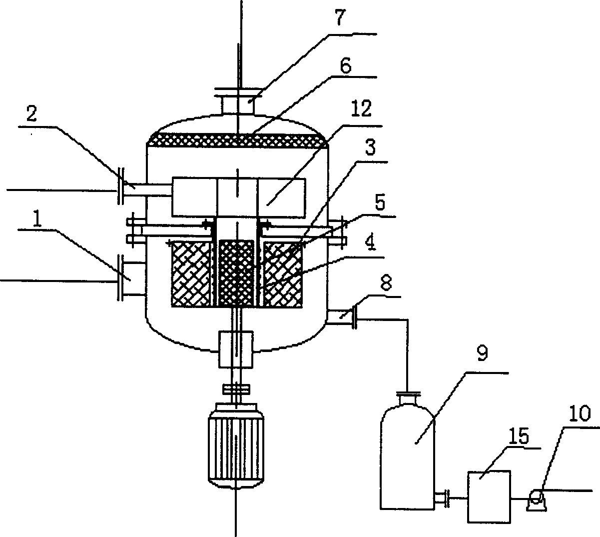
[0041] The schematic diagram of the technological process adopted by the high-gravity rotating bed reactor is as attached figure 1 shown. Air is tangentially introduced into the reactor from the gas phase inlet 1 of the high-gravity rotating bed reactor, water is introduced into the reactor through the liquid phase inlet 2 of the high-gravity rotating bed reactor, and sprayed on the porous packing layer by the liquid distributor 4 3, the specific surface area of ​​685m2 is filled on the inner edge of the rotor 2 / m 3 , small corrugated packing with a porosity of 96.4% and a radial th...

Embodiment 2

[0046] Coking dry gas in refineries contains a certain amount of carbon powder and hydrogen sulfide as well as a large amount of hydrogen, nitrogen, C 1 、C 2 and a small amount of C 3 , this dry gas will enter the subsequent hydrogen production workshop to produce hydrogen, so the content of carbon powder, hydrogen sulfide and gas liquid entrainment are required to be as low as possible, and the method of the present invention is used to remove the carbon powder and carbon powder contained in the coking dry gas. hydrogen sulfide. The coking dry gas flow rate mentioned therein: 10 tons / hour, H 2 S content: 8300-22000mg / Nm 3 , Toner content: 5g / Nm 3 , particle size range: 0.2-20μm, pressure: 1MPa; both desulfurizer and dedusting agent are 30% MDEA (methyldiethanolamine) solution, liquid flow rate: 20 tons / hour, H 2 S content: 1.56g / l; the rotating speed of the high-gravity rotating bed reactor is 960 rpm.

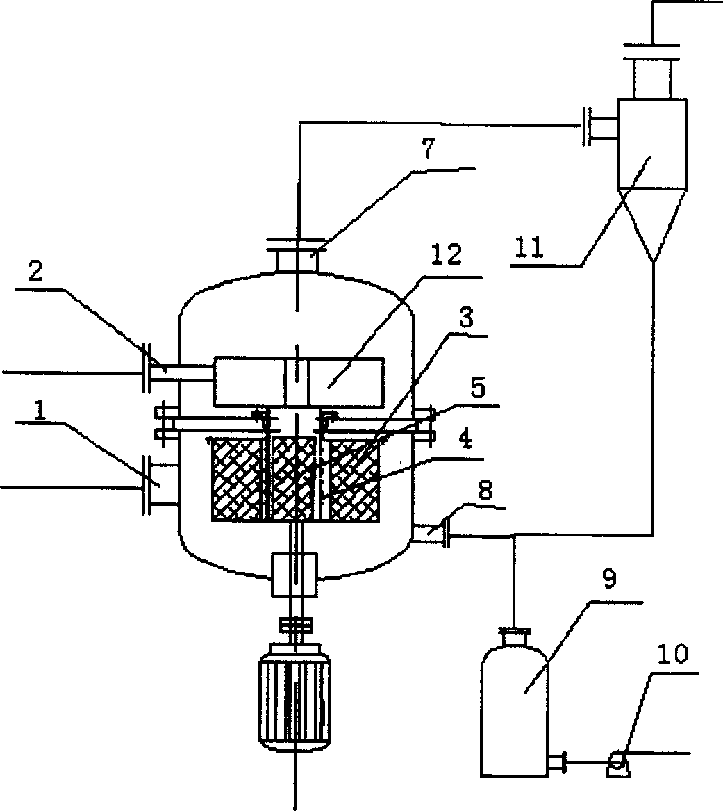
[0047] The schematic diagram of the technological process adopted ...


PUM

PropertyMeasurementUnit
pore sizeaaaaaaaaaa
pore sizeaaaaaaaaaa
thicknessaaaaaaaaaa

Abstract

The method of eliminating impurity from gas phase includes introducing the eliminating agent for gas phase and the eliminating agent for liquid phase into the super-gravitational rotating bed reactor separately via the gas phase inlet and the liquid phase inlet, eliminating foam from the gas after eliminating impurity with the defoaming unit before exhaust from the reactor, and draining the liquid phase rich in solid powder and/or H2S via the liquid phase outlet. The present invention also sets defoaming section in the outlet end of the reactor to eliminate liquid foam from the gas phase via two-stage defoaming, including the first stage defoaming in the rotary deforaming device and the second stage defoaming in the fixed or rotating defoaming device. The present invention makes it possible to eliminate solid dust and H2S from gas phase simultaneously, and this shortens the technological process, lowers the cost and power consumption, and reduces the covered area.

Description

technical field [0001] The invention relates to a method for purifying gas, in particular to a method for removing impurities in the gas phase by using a rotating bed supergravity field technology. Background technique [0002] In industry, the impurities in the gas phase, such as solid dust, hydrogen sulfide, etc., will not only block and corrode the pipeline during the production process, but also affect the purity of the gas-liquid phase products and the subsequent processing process, causing pollution after discharge environment and therefore must be removed. [0003] The dust removal devices commonly used in industry can be divided into the following six categories according to their different dust removal mechanisms: [0004] 1. Gravity dust collectors can only be used to separate dust particles above 50 μm, and are generally used for pre-dust removal of coarse dust particles; their characteristics are: small pressure loss, low operating costs, but huge equipment and ...

Claims


Application Information

Patent Timeline
Patent Type & Authority Applications(China)
IPC IPC(8): B01D47/00B01D53/78
Inventor 杨元一李振虎程建民郭锴戴伟陈硕茅文星廖丽华陈建锋郭奋
Owner CHINA PETROLEUM & CHEM CORP
Why Eureka
Try Eureka