
Polishing machine

A grinding machine and frame technology, which is applied to grinding machines, grinding workpiece supports, grinding/polishing equipment, etc., can solve the problems of physical exertion, low production efficiency, high labor intensity of workers, etc., and achieve good grinding effect and semi-automatic grinding. , the effect of simple structure

Inactive Publication Date: 2014-08-06
KUNSHAN SHANGDAZHI MACHINERY
View PDF6 Cites 9 Cited by
  • Summary
  • Abstract
  • Description
  • Claims
  • Application Information

AI Technical Summary

Problems solved by technology

For this process, the common method is still manual operation. The specific operation is that the operator holds sandpaper or a grinding block to move and rub against the inner and outer surfaces of the pot made of this carbon material, so as to grind and polish. Manual operation has the following disadvantages: on the one hand, the labor intensity of workers is high, and workers are prone to occupational diseases; on the other hand, the grinding speed cannot be controlled, and the production efficiency is low
[0003] Patent No. 201120300484.3 discloses a grinding machine, which includes a frame, a drive unit, a rotating shaft and a balance plate connected to one end of the rotating shaft for supporting the object to be polished. When in use, the product to be ground or polished is placed on the balance plate On the other hand, when the product rotates with the balance plate, the operator holds the abrasive leather or the grinding block close to the surface of the pot body to produce relative movement and friction, so as to grind and polish the surface of the pot, but it is impossible to grind and polish the inside of the pot body Although the labor intensity of the workers can be reduced to a certain extent without the need for the workers to move back and forth with their own force, it still requires the workers to hold the gauze or a grinding block next to the machine to grind and polish by their relative friction, which still takes a certain amount of time. Physical strength, not suitable for mass production

Method used


Image

  • Polishing machine
  • Polishing machine

Examples


Embodiment Construction

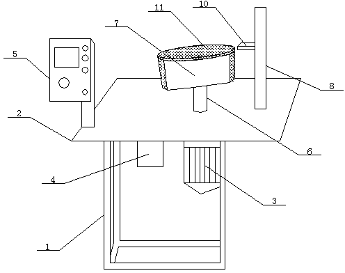
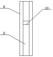
[0012] See figure 1 , figure 2 , This specific implementation adopts the following technical solutions: it includes a frame 1, a workbench 2, a motor 3, a speed regulating device 4, a control panel 5, a rotating shaft 6, a rotating disk 7, a workbench 2 is provided on the frame 1, and a motor 3 is set under the workbench 2, a speed regulating device 4 is set on one side of the motor 3, a control panel 5 is set above the workbench 2, and the upper end of the motor 3 is connected with a rotating disk 7 through a rotating shaft 6. One side of the rotating disk 7 A column 8 is provided, a slide groove 9 is provided on the side of the column 8 corresponding to the rotating disk 7, and a fixed rod 10 is movably provided in the slide groove 9.

[0013] The rotating disk 7 is a cylinder, and a polishing material layer 11 is provided on the upper end and the side surface of the rotating disk 7.

[0014] The polishing material layer 11 is made of SK4 steel.

[0015] In this specific embodim...


PUM


Abstract

A polishing machine relates to the field of production equipment of carbon pans. A working platform is arranged on a rack, a motor is arranged below the working platform, a speed regulating device is arranged on one side of the motor, a control panel is arranged above the working platform, the upper end of the motor is connected with a rotary disc through a rotating shaft, an upright is arranged on one side of the rotary disc, a sliding chute is formed in one side of the upright corresponding to the rotary disc, and a fixing rod is movably arranged in the sliding chute. The rotary disc is a cylinder, and polishing material layers are arranged on the side surface and at the upper end of the rotary disc respectively. The polishing material layers are made of a steel SK4. The polishing machine is simple in structure, effectively solves the problem that a worker needs to take gauze or a polishing block to polish beside a machine through the relative friction, is good in polishing effect, saves time and labor, and achieves semi-automatic polishing in the true sense.

Description

Technical field: [0001] The invention relates to the technical field of polishing equipment, in particular to a polishing machine. Background technique: [0002] At present, there is a pot made of carbon material. This pot is made of carbon material through multiple processes. One of the processes is to polish and polish the inner and outer surfaces of the pot to make the inner surface of the pot more flat. Non-stick pan, the outer surface is smoother, non-rough and more beautiful. For this process, the commonly used method is still manual operation. The specific operation is that the operator holds sandpaper or grinding blocks to move and rub against the inner and outer surfaces of the pot made of this carbon material to carry out grinding and polishing. Manual operation has the following shortcomings: on the one hand, the labor intensity of workers is high, and workers are prone to occupational diseases; on the other hand, the polishing speed cannot be controlled and the produ...

Claims


Application Information

Patent Timeline
IPC IPC(8): B24B19/22
CPCB24B19/22B24B41/061
Inventor 张荣磊
Owner KUNSHAN SHANGDAZHI MACHINERY
Learn More