Eureka AIR delivers breakthrough ideas for toughest innovation challenges, trusted by R&D personnel around the world.

Buffer For Brushes

A technology of buffers and brushes, which is applied in the field of buffers of brushes, can solve problems such as multiple buffer spaces, and achieve the effect of simple installation and good operation

Active Publication Date: 2014-08-06
ZAHORANSKY AG
View PDF5 Cites 2 Cited by
  • Summary
  • Abstract
  • Description
  • Claims
  • Application Information

AI Technical Summary

Problems solved by technology

[0003] Such buffers usually have a conveyor belt with a brush holder or an endless chain, so that the buffer requires relatively much space

Method used


Image

  • Buffer For Brushes
  • Buffer For Brushes
  • Buffer For Brushes

Examples


Embodiment Construction

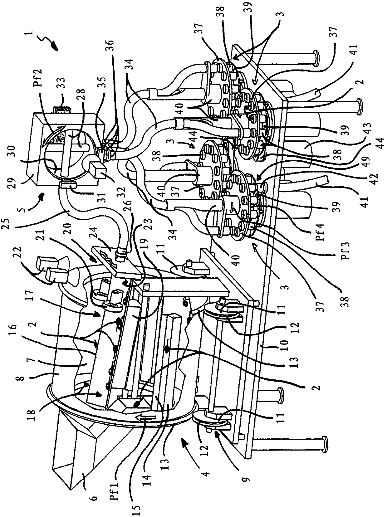
[0060] according to figure 1 The buffer for brushes 2 , which is marked overall with 1 , has four buffer magazines 3 as well as a separating device 4 and a sorting adapter 5 .

[0061] A previously produced brush 2 (here a screw-in brush such as an interdental toothbrush or a mascara brush) is introduced into the interior 7 of the drum 8 of the separating device 4 via the funnel-shaped filling opening 6 . The drum 8 is shown partially cut away for a better overview. Also, for a clearer view, the lateral ends of said drum 8 are shown open. Usually the lateral ends are closed, for example covered with a plate, in order to prevent the brush 2 from falling out of the inner cavity 7 .

[0062] picture figure 1 As shown in , the drum 8 can be formed cylindrically with a circular cross section. However, the drum 8 can also be assembled from a plurality of plate segments and thus have a polygonal cross-section.

[0063] The roller 8 is arranged on a table 10 via a roller bearing ...


PUM


Abstract

The buffer has a hollow-cylinder-like brush holder whose sides are provided with several circular buffer wheels. The front end of the hollow-cylinder-like brush holder is positioned with a supply channel, and longitudinal end is provided with a discharge channel arranged in a removal point, such that the buffer wheels and discharge channel are arranged relatively to each other. The discharge channel has a suction nozzle which generates air stream for transporting brush of brush holder.

Description

technical field [0001] The invention relates to a damper for brushes, in particular screw-in brushes, having a damper magazine with a plurality of brush receptacles. Background technique [0002] Such buffers are well known and are used to decouple processing devices from one another. For example, such a damper can be arranged between the device for plastic-molding the brush body and the drilling device. In the event of a failure of one of the devices, the other device can nonetheless continue to work, since the brushes can be inserted into the buffer from the plastic spraying device or removed from the buffer by the drilling device. It is also possible to balance the different operating speeds of the devices and to feed the brushes to devices arranged downstream of the buffer at a constant rate. [0003] Such buffers usually have a conveyor belt with brush receptacles or an endless chain, so that they require relatively much space. [0004] Previously known brush holders...

Claims


Application Information

Patent Timeline
Patent Type & Authority Applications(China)
IPC IPC(8): B65G47/74
CPCA46D3/04A46D3/08B65G47/1428B65G51/02A45D34/04B65G51/00
Inventor P·斯泰纳布伦纳M·文德勒C·伊维托斯基M·塞格尔M·格罗斯曼
Owner ZAHORANSKY AG
Why Eureka
Eureka Blog
Learn More