Combination column and combination beam frame with internally-arranged high-strength concrete core columns and construction method thereof

A technology of high-strength concrete and construction methods, which is applied in the direction of architecture and building construction, can solve the problems of large section size and difficult layout of prestressed tendons, etc., and achieve the effects of reducing section size, shortening construction period, and large span

Inactive Publication Date: 2014-08-06
NORTHEAST GASOLINEEUM UNIV
View PDF6 Cites 8 Cited by
  • Summary
  • Abstract
  • Description
  • Claims
  • Application Information

AI Technical Summary

Problems solved by technology

[0003] The purpose of the present invention is to provide a composite column composite beam frame with a built-in high-strength concrete core column, which is used to solve the problem that the existing general reinforced concrete column has a large section size and the prestressed tendons in the composite beam are difficult to arrange at the nodes. Another purpose of this is to provide a construction method for this composite column composite beam frame with built-in high-strength concrete core columns

Method used


Image

  • Combination column and combination beam frame with internally-arranged high-strength concrete core columns and construction method thereof
  • Combination column and combination beam frame with internally-arranged high-strength concrete core columns and construction method thereof
  • Combination column and combination beam frame with internally-arranged high-strength concrete core columns and construction method thereof

Examples


Embodiment 1

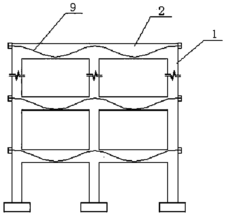
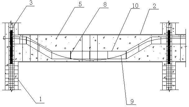
[0046] like figure 1 As shown, the composite column composite beam frame with built-in high-strength concrete core column has a built-in asymmetrical steel or plastic bone prestressed concrete composite beam, a reinforced concrete composite column 1 with a built-in core column 3, and the composite beam 2 is horizontally arranged on Between composite columns 1, the two are connected by nodes at the intersection. to combine Figure 8 , Figure 15 As shown, the prestressed tendon 9 at the beam-column node passes through both sides of the core column 3, and is stretched and anchored at the end of the composite column. The H-shaped steel or plastic bone in the composite beam and the vertical steel / plastic bone in the core column The bone connector 4 is connected, of course, the H-shaped steel or plastic bone in the composite beam can also be connected with the core column vertical core steel pipe 12 or the vertical core plastic tube, see Figure 9 . In this embodiment, the same...

Embodiment 2

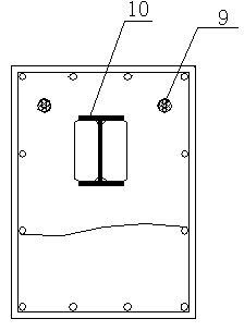
[0058] This composite beam frame with different strength composite columns with built-in core columns has a built-in asymmetrical steel or plastic bone prestressed concrete composite beam 2, a reinforced concrete composite column 1 with built-in core columns, and the composite beam 2 is horizontally arranged on the composite column 1 Between them, the two are connected by nodes at the intersection; the core column 3 is formed by pouring longitudinal bars 6, stirrups 7, and concrete 5 together, the longitudinal bars 6 are distributed around the core column 3, and the stirrups 7 are wrapped in the longitudinal bars 6 In addition, the core column 3 is placed in a reinforced concrete column, and the density of the stirrups 7 in the core column is greater than the density of the stirrups in the reinforced concrete column; the cross-section of the composite beam 2 is rectangular, and the steel bone 10 or plastic bone is H-shaped , the steel frame 10 or plastic frame is provided with ...

Embodiment 3

[0066] This composite column composite beam frame with built-in high-strength concrete core column has a built-in asymmetrical steel or plastic bone prestressed concrete composite beam 2, a reinforced concrete composite column 1 with a built-in core column, and the composite beam 2 is horizontally arranged on the composite column 1 Between them, the two are connected by nodes at the intersection; the core column 3 is formed by pouring longitudinal bars 6, stirrups 7, and concrete 5 together, the longitudinal bars 6 are distributed around the core column 3, and the stirrups 7 are wrapped in the longitudinal bars 6 In addition, the core column 3 is placed in a reinforced concrete column, and the density of the stirrups 7 in the core column is greater than that of the reinforced concrete column; the cross-section of the composite beam 2 is rectangular, and the built-in steel bone 10 or plastic bone is H type, the steel frame 10 or plastic frame is provided with transverse stiffeners...


PUM


Abstract

The invention relates to a combination column and combination beam frame with internally-arranged high-strength concrete core columns and a construction method of the combination column and combination beam frame. The special strong combination column and combination beam frame with the internally-arranged core columns is provided with internally-arranged asymmetric steel rib or plastic rib prestressed concrete combination beams and reinforcing bar concrete combination columns with the internally-arranged core columns, the combination beams are horizontally arranged between the combination columns, and the combination beams are connected with the combination columns at intersections through joints. The core columns are formed by pouring longitudinal ribs, stirrups and concrete together, the longitudinal ribs are distributed around the core columns and are wrapped by the stirrups, and the core columns are placed in the reinforcing bar concrete columns. Transverse stiffening ribs are arranged on steel ribs or plastic ribs in the combination beams, the steel ribs or the plastic ribs at the midspan positions are arranged on the lower portions of the combination beams, the steel ribs or the plastic ribs on supports are arranged on the upper portions of the combination beams, and prestressed ribs are arranged in the combined beams in the length direction. The prestressed ribs on the beam and column joints penetrate through two sides of the core columns, and are tensioned and anchored at the ends of the combination columns. The section size of the columns can be obviously reduced, too wide columns are prevented from existing in a system, and the prestressed ribs in the combination beams can generate evenly-distributed counterforce to eliminate part of external loads.

Description

1. Technical field: [0001] The invention relates to a building frame structure in the field of civil engineering structures, in particular to a composite column composite beam frame with a built-in high-strength concrete core column and a construction method thereof. 2. Background technology: [0002] Conventional building frame structures are mostly reinforced concrete frames and steel frames, the achievable spans are small, and the bearing capacity of components is low, which has great limitations in practical engineering applications. In recent years, with the development of higher buildings, larger spans and heavy loads, conventional structural systems are facing new challenges. People began to build a structural system with greater rigidity and stronger bearing capacity. Steel bones were added to the concrete, and the concrete and steel bones were bonded together to form a combined structure with high rigidity and convenient construction. Due to the deficiencies and de...

Claims


Application Information

Patent Timeline
Patent Type & Authority Applications(China)
IPC IPC(8): E04B1/30
Inventor 计静张文福张云峰马令勇赵文艳袁朝庆
Owner NORTHEAST GASOLINEEUM UNIV
Why Eureka
Try Eureka