A vehicle-mounted vibration-damping camera mount

A camera frame and camera technology, applied in the field of camera frames, can solve problems such as blurred photos, camera failures, and camera frames that cannot buffer shocks, etc., and achieve the effects of small size, convenient production, and simple structure

Inactive Publication Date: 2016-04-27
SHANGHAI UNIV OF ENG SCI
View PDF4 Cites 1 Cited by
  • Summary
  • Abstract
  • Description
  • Claims
  • Application Information

AI Technical Summary

Problems solved by technology

[0003] (1) The camera frame cannot buffer the impact caused by the relatively large unevenness of the road surface
When the camera is shooting, this has a great impact on the video quality, but the biggest harm is to damage the mechanical structure inside the camera, which will cause the camera to malfunction
[0004] (2) Affect photography and video quality
The camera frame can't dampen these vibrations. Firstly, this affects the quality of photography (photos taken with a sense of blur); secondly, when taking pictures, the video screen also keeps jumping with the vibration of the car body.
In the case of high speed, the photo will be severely blurred, and the video screen with frequent jumps may cause the viewer to feel dizzy

Method used


Image

  • A vehicle-mounted vibration-damping camera mount
  • A vehicle-mounted vibration-damping camera mount
  • A vehicle-mounted vibration-damping camera mount

Examples


Embodiment

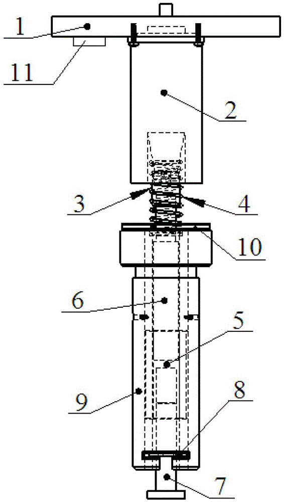
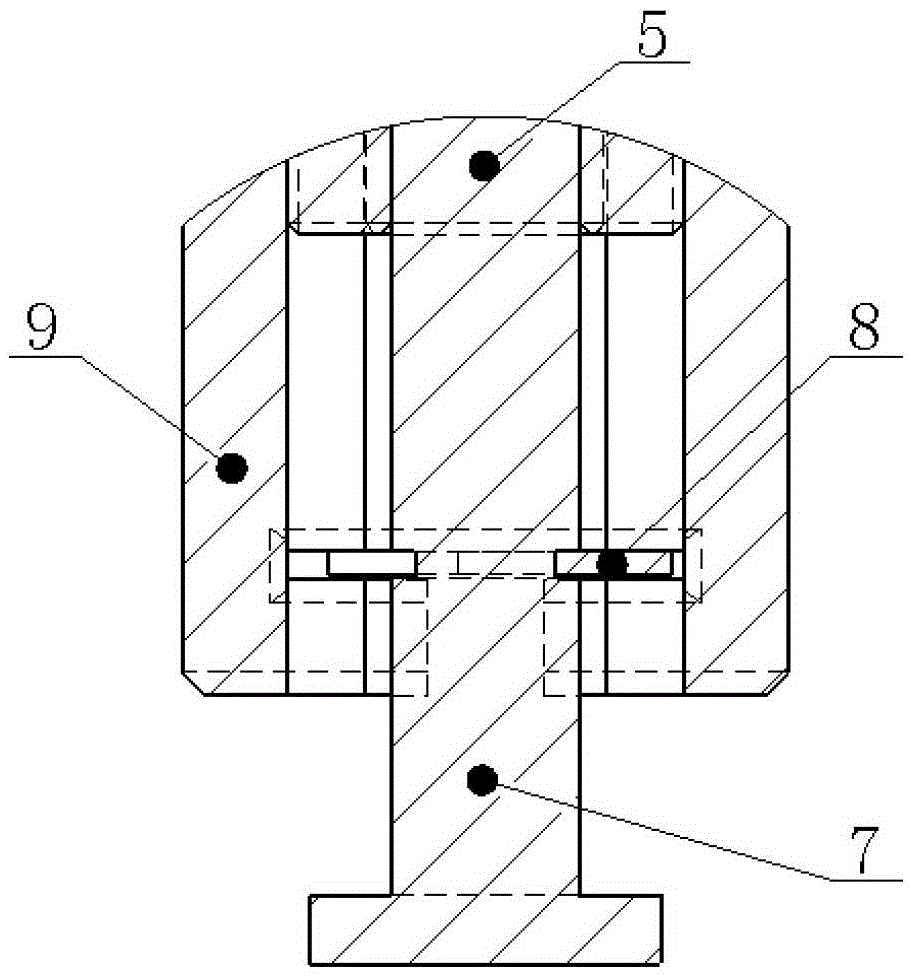
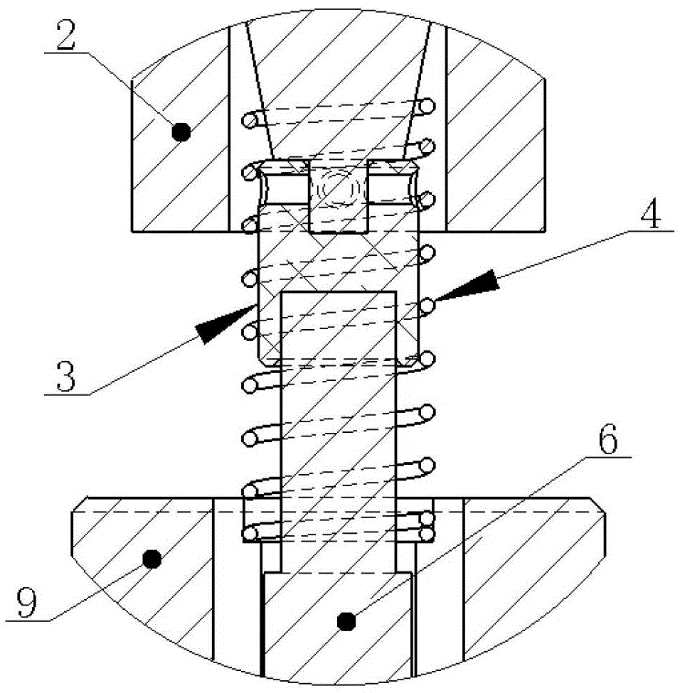
[0031] A vehicle-mounted vibration reduction camera mount, such as Figure 1 to Figure 4 As shown, the camera frame includes a camera platform 1, a sensing and control center 11, an electromagnet 2, a damper 6, a lower base 9, a spring 4 and a permanent magnet 10, wherein the electromagnet 2 is connected to the lower end of the camera platform 1 , the lower end of the damper 6 is sleeved inside the lower base 9, the upper end of the damper 6 is connected to the electromagnet 2 through the connector 3, the spring 4 is sleeved outside the upper end of the damper 6, and the upper and lower ends of the spring 4 are connected to the electromagnet 2 and the lower end respectively. The base 9 abuts, the sensing and control center 11 is arranged on the lower side of the camera platform 1 and connected with the electromagnet 2 , and the permanent magnet 10 is arranged on the top of the lower base 9 . The sensing and control center 11 includes an acceleration sensor, a single-chip micro...


PUM


Abstract

The invention relates to a vehicular damping camera holder. The vehicular damping camera holder comprises a camera supporting table, a sensing and control center, an electromagnet, a damper, a lower base, a spring and a permanent magnet. The electromagnet is connected to the lower end of the camera supporting table, the lower end of the damper internally sleeves the lower base, the upper end of the damper is connected with the electromagnet through a connector, the spring sleeves the outer side of the upper end of the damper, the upper end and the lower end of the spring are abutted against the electromagnet and the lower base respectively, the sensing and control center is arranged on the lower side of the camera supporting table and connected with the electromagnet, and the permanent magnet is arranged at the top end of the lower base. After vibration occurs, vibration energy is partially absorbed and consumed by the damper and the spring, the sensing and control center outputs voltage to the electromagnet after vibration of the camera supporting table is detected, magnetic fields are generated around the magnets, and vibration energy is further absorbed and consumed under interaction force between the magnetic field around the electromagnet and the magnetic field around the permanent magnet. Compared with the prior art, the vehicular damping camera holder has the advantages of simple structure, small size, effectiveness in damping and the like.

Description

technical field [0001] The invention relates to a camera frame, in particular to a vehicle-mounted vibration reduction camera frame. Background technique [0002] At present, there are many small and durable bicycle camera frames in the cycling photography equipment market, and there are also various bicycle camera frames DIYed by riders. But they all have one thing in common: there is a rigid connection between the camera and the camera frame. This leads them to two major flaws: [0003] (1) The camera frame cannot buffer the impact caused by the relatively large unevenness of the road surface. When the camera is shooting, this has a great impact on the video quality, but the biggest harm is to damage the mechanical structure inside the camera, which will cause the camera to malfunction. [0004] (2) Affect photography and camera quality. When the bicycle is running on a relatively smooth road, there is also continuous vibration. The camera frame also can't play a damp...

Claims


Application Information

Patent Timeline
Patent Type & Authority Patents(China)
IPC IPC(8): F16M13/02F16F15/03F16F15/04
Inventor 廖爱华王伟生许唯杰
Owner SHANGHAI UNIV OF ENG SCI
Why Eureka
Try Eureka