LED light source system and LED lighting device
A technology of LED light source and LED chip, applied in the field of light source, can solve problems such as unresolved problems and user troubles
- Summary
- Abstract
- Description
- Claims
- Application Information
AI Technical Summary
Problems solved by technology
Method used
Image


Examples
Embodiment 1
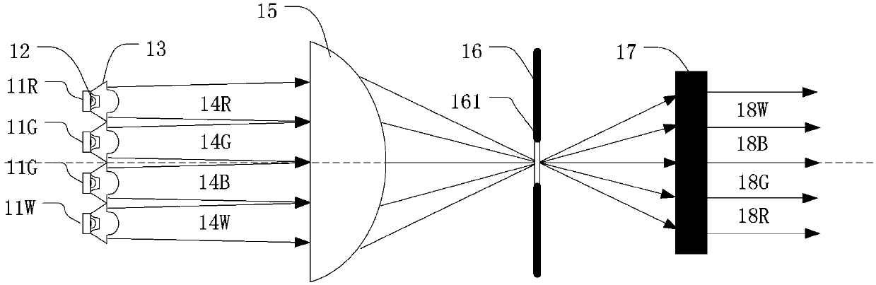
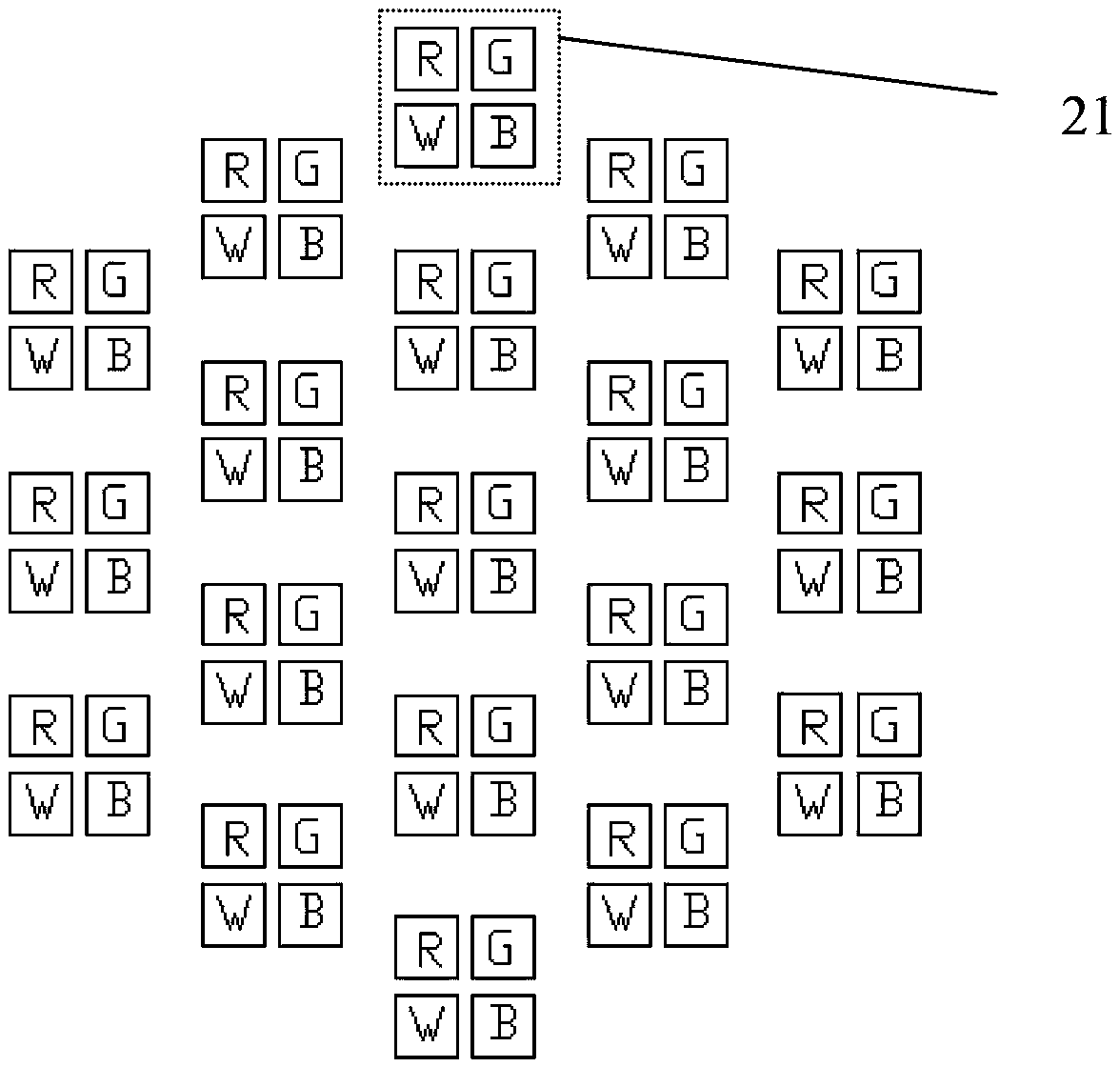
[0043] Figure 2aIt is an arrangement diagram of LED chips in the LED light source system of this embodiment. In this embodiment, LED chips of different colors form a chip group and are fixed on a unit to form an LED unit module 21 , and a plurality of LED unit modules form a multi-color LED unit module array. Wherein, each LED unit module includes LED chips of each color used in the multi-color LED unit module array. Figure 2b for Figure 2a Arrangement diagram of different LED chips on any of the LED unit modules, wherein, 21 is the LED unit module, which consists of 4 different
[0044] The LED chip consists of a red LED chip 21R, a green LED chip 21G, a blue LED chip 21B and a white LED chip 21W, which are fixed on the same heat-conducting substrate 213 . The thermally conductive substrate 213 can be made of aluminum oxide, aluminum nitride and other thermally conductive ceramics, as long as it has a sufficiently high thermal conductivity and an insulating surface laye...
Embodiment 2
[0062] In the first embodiment, a fly-eye lens is used in the light source system in order to realize the spatial homogenization of the projected spot, but the cost of using the fly-eye lens is high and the system is complicated; this embodiment will use another way to homogenize the light Instead of fly-eye lenses.
[0063] In this embodiment, the LED chip groups in each LED unit module are imaged on a predetermined surface by overlapping the collimator lens and the condenser lens to form a mixed spot. The distribution of LED chips of different colors makes the LED chips of any color have approximately the same distribution in each position of each LED unit module, so that the mixed light spot has good uniformity. For example, if Figure 4b As shown, the blue LED chip (identified as B in the figure) has four different positions in each LED unit module, which are the upper left corner, lower left corner, upper right corner and lower right corner, and the blue LED chip is in e...
Embodiment 3
[0068] In the above two embodiments, for the LED chip of each color, since the chip deviates from the optical axis relative to the collimating lens (such as image 3 The LED chip 211 shown in is deviated from the optical axis 221 of the collimating lens 22), and the projected light spot of a single chip is eccentric relative to the central optical axis of the entire light source system, which will affect the uniformity of the light spot formed by the LED light source system on the predetermined surface adverse effects on sex.
[0069] In this embodiment, on the basis of the second embodiment, the fly-eye lens group in the first embodiment is used in combination, and the light uniformity effect will be better. Figure 5a In the case of a fly-eye lens group, for Figure 2a The arrangement of the LED unit modules shown is the result of simulating the red LED chip; Figure 5b Also in the case of a fly eye lens group, for Figure 4b The arrangement of the LED unit modules shown ...
PUM
 Abstract
Description
Claims
Application Information
 - Generate Ideas
- Intellectual Property
- Life Sciences
- Materials
- Tech Scout
- Unparalleled Data Quality
- Higher Quality Content
- 60% Fewer Hallucinations
Browse by: Latest US Patents, China's latest patents, Technical Efficacy Thesaurus, Application Domain, Technology Topic, Popular Technical Reports.
© 2025 PatSnap. All rights reserved.Legal|Privacy policy|Modern Slavery Act Transparency Statement|Sitemap|About US| Contact US: help@patsnap.com