Pulse width modulation control method and pulse width modulation control device

A pulse width modulation, pulse width technology, applied in the field of control, can solve the problems of easy fluctuation, deviation from expected value, damage to the switch tube, etc.

Inactive Publication Date: 2014-08-06
SHENZHEN POLYTECHNIC
View PDF6 Cites 2 Cited by
  • Summary
  • Abstract
  • Description
  • Claims
  • Application Information

AI Technical Summary

Problems solved by technology

However, this method has the following disadvantages: the capacitor voltage V C vs. peak bus voltage V DC is not a linear relationship, although it can control the capacitor voltage V C remains constant, but V DC It will change with the change of the direct duty cycle, the peak value of the bus voltage V DC It is easy to fluctuate or deviate from the expected value, and the bus voltage peak value V DC It may damage the switch tube when it is too high

Method used


Image

  • Pulse width modulation control method and pulse width modulation control device
  • Pulse width modulation control method and pulse width modulation control device
  • Pulse width modulation control method and pulse width modulation control device

Examples


Embodiment approach

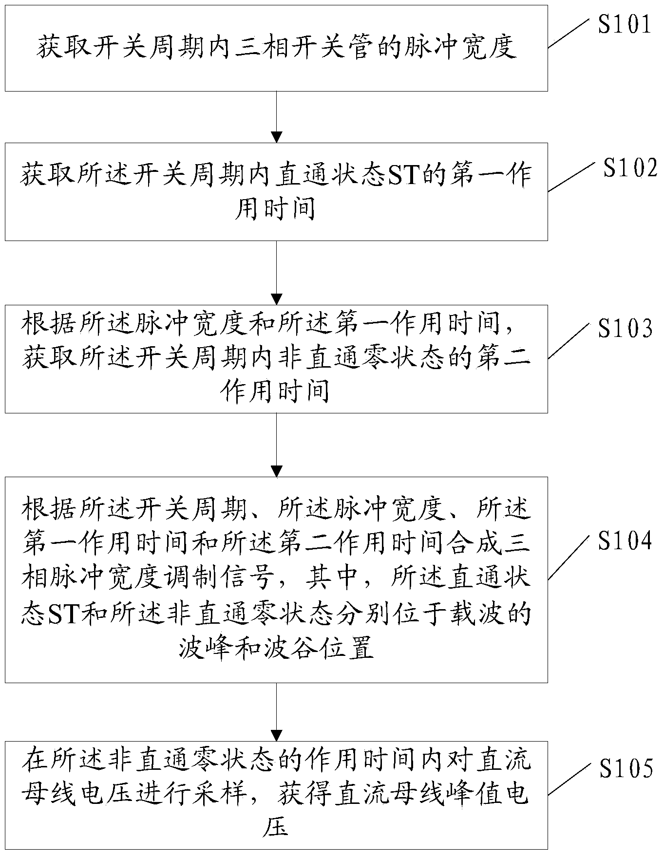
[0081] As a possible implementation manner, the method further includes:

[0082] S105: Sampling the DC bus voltage at the moment when the non-through zero state is applied to obtain the DC bus peak voltage.

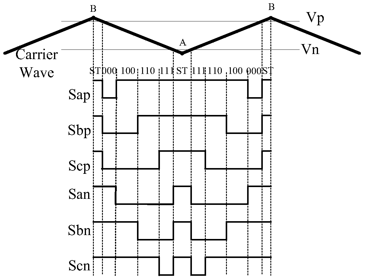
[0083] Since the through state ST and the non-through zero state are respectively located at the apex and valley point of the carrier, that is, the through state ST and the non-through zero state are separated by the effective state, and the through state only appears once in a switching cycle, see Figure 4 , Figure 4 It is a schematic diagram of a state vector provided by an embodiment of the present invention. It can be seen from the figure that the sequence of switching state changes in the switching period Ts is: V 0 (000), V 4 (100), V 6 (110), through state ST, V 6 (110), V 4 (100), V 0 (000). Since the through duty cycle is limited in practical applications (generally less than 30%, that is, the through state ST has a shorter action time), the through state ST is onl...


PUM


Abstract

The invention discloses a pulse width modulation control method. The pulse width modulation control method includes: acquiring a pulse width of a three-phase switch in a switching period; acquiring a first action time of a shoot-through state ST in the switching period; acquiring a second action time of a non-shoot-through null state in the switching period according to the pulse width and the first action time; synthesizing a three-phase pulse width modulation signal according to the switching period, the pulse width, the first action time and the second action time, wherein the shoot-through state ST and the non-shoot-through null state are at positions of a crest and a trough of a carrier wave respectively. Correspondingly, the invention further discloses a PWM (pulse width modulation) control device. Using the pulse width modulation control method and the pulse width modulation control device can directly measure crest voltage on a direct-current busbar to further control busbar voltage directly.

Description

Technical field [0001] The present invention relates to the field of control technology, in particular to a pulse width modulation control method and device. Background technique [0002] Inverter (Inverter) is a device or equipment that converts direct current (battery, storage battery) into alternating current (usually 220V, 50Hz sine wave), including voltage source inverter, current source inverter and Z source Inverter (Z-source inverter, referred to as ZSI). Generally, the inverter control method adopts the pulse width modulation (Pulse Width Modulation, PWM) control method. In the traditional PWM control method, the state of the switch tube includes 8 non-through states, of which 6 valid states V1 (001 ), V2(010), V3(011), V4(100), V5(101), V6(110) and two zero states V0(000), V7(111), 1 means on, 0 means off . In voltage source inverters and current source inverters, the states of the three switch tubes in the lower bridge arm are opposite to those of the three switch t...

Claims


Application Information

Patent Timeline
Patent Type & Authority Applications(China)
IPC IPC(8): H02M7/5395
Inventor 钟宇明徐殿国文励洪常江吴志敏
Owner SHENZHEN POLYTECHNIC
Why Eureka
Try Eureka