Numerically-controlled busbar punching machine
A punching machine and busbar technology, used in metal processing equipment, forming tools, manufacturing tools, etc., can solve the problems of maintenance, inconvenient maintenance, unfavorable processing environment, complex punch structure, etc., to achieve convenient operation and avoid excessive temperature. High and easy maintenance effect
- Summary
- Abstract
- Description
- Claims
- Application Information
AI Technical Summary
Problems solved by technology
Method used
Image


Examples
Embodiment Construction
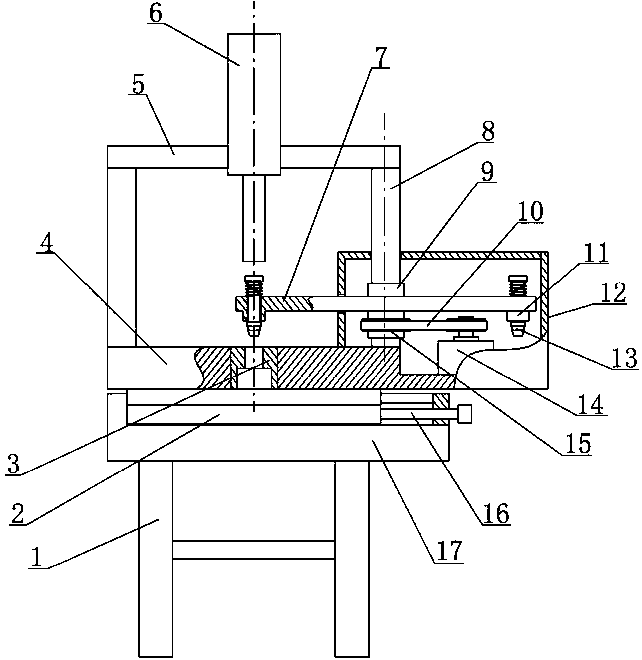
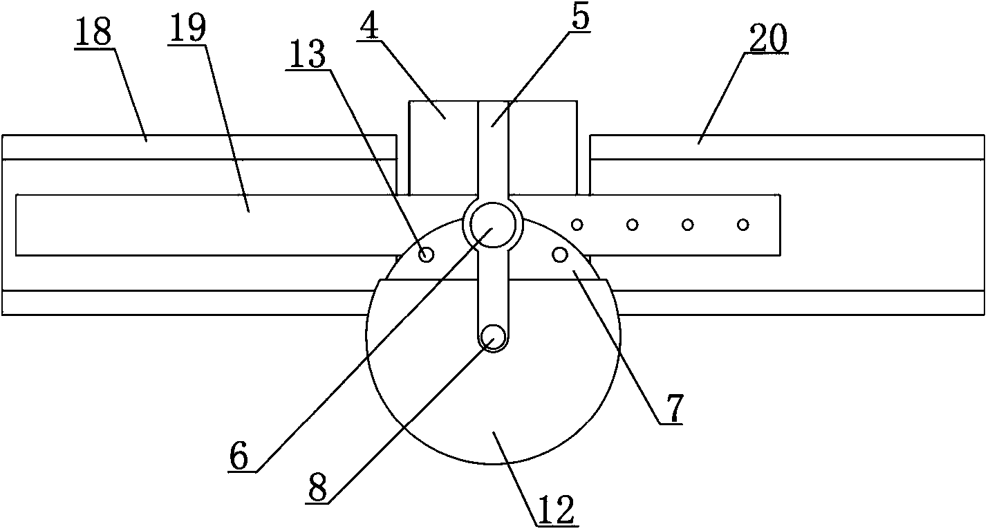
[0013] see figure 1 , 2 , 3, a numerically controlled busbar punching machine, comprising a frame 1, a seat plate 17 is installed above the frame 1, a workbench 4 is arranged above the seat plate 17, and a workbench 4 is arranged between the seat plate 17 and the workbench 4 There is a slide rail device 2 and a lead screw mechanism 16 that drives the two to move relative to each other along the direction of the slide rail; the middle part of the workbench 4 is fixed with a lower mold 3, and the top of the workbench 4 is provided with a beam 5 supported by two columns 8 , a vertical oil cylinder 6 is fixed on the beam 5, and the oil cylinder 6 is located directly above the lower mold 3; a horizontally placed turntable 7 is arranged above the workbench 4, and the horizontal position of the turntable 7 is at Between the oil cylinder 6 and the lower mold 3, the underside of the rotary disk 7 is provided with a concentric driven wheel 15, and the driven wheel 15 is connected with ...
PUM
 Abstract
Description
Claims
Application Information
 - Generate Ideas
- Intellectual Property
- Life Sciences
- Materials
- Tech Scout
- Unparalleled Data Quality
- Higher Quality Content
- 60% Fewer Hallucinations
Browse by: Latest US Patents, China's latest patents, Technical Efficacy Thesaurus, Application Domain, Technology Topic, Popular Technical Reports.
© 2025 PatSnap. All rights reserved.Legal|Privacy policy|Modern Slavery Act Transparency Statement|Sitemap|About US| Contact US: help@patsnap.com