Lock beam molding cutting device

A cutting device and pulley technology, which is applied to feeding devices, metal processing machinery parts, metal processing equipment, etc., can solve the problems of high labor cost and low manufacturing efficiency of lock beams, and achieve the effect of simple structure and high efficiency.

Inactive Publication Date: 2014-08-13
TONGXIANG XILIANG TIN CANS
View PDF6 Cites 13 Cited by
  • Summary
  • Abstract
  • Description
  • Claims
  • Application Information

AI Technical Summary

Problems solved by technology

However, there is no automatic cutting and forming machine equipment on the market at present, the manufacturing efficiency of the lock beam is too low, and the labor cost is high

Method used


Image

  • Lock beam molding cutting device

Examples


Embodiment Construction

[0011] The present invention will be further described in detail below in conjunction with the accompanying drawings and examples. The following examples are explanations of the present invention and the present invention is not limited to the following examples.

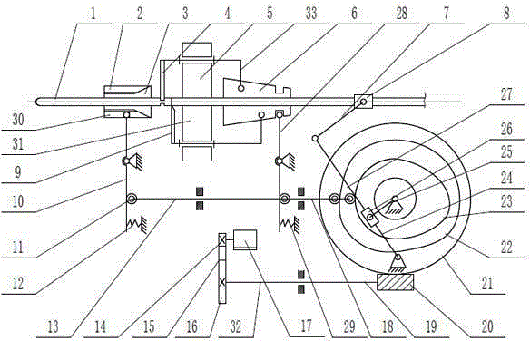
[0012] Such as figure 1 As shown, a lock beam forming cutting device includes a power transmission mechanism 32, a feeding mechanism 27, a clamping mechanism 30 and a cutting mechanism 31. Described power transmission mechanism 32 comprises motor 17, pulley one 14, belt 15, pulley two 16, shaft 19, worm screw 20 and turbine 21, and described motor 17 is connected with pulley one 14 concentrically, and described pulley one 14 and pulley The two pulleys 16 are connected by a belt 15, the two pulleys 16 and the worm 20 are coaxially arranged at the two ends of the shaft 19, and the worm 20 and the worm gear 21 mesh. Described feeding mechanism 27 comprises crank 25, slide block 26, connecting rod one 24, connecting ro...


PUM


Abstract

The invention provides a lock beam molding cutting device and belongs to the technical field of mechanical machining equipment. The lock beam molding cutting device comprises a power transmission mechanism, a feeding mechanism, a clamping mechanism and a cutting mechanism; the power transmission mechanism comprises a motor, a belt wheel I, a belt, a belt wheel II, a shaft, a worm and a turbine; the feeding mechanism comprises a crankshaft, a slider, a connection rod I, a connection rod II and a feeder; one end of the crankshaft is hinged to the slider; the clamping mechanism comprises a cam I, a push rod I, a swing rod I, a conical bush and a clamping pawl; the axes of the conical cam, the feeder and the clamping pawl are positioned in the same horizontal line; the conical cam is arranged right ahead of the feeder; the clamping pawl is arranged in the right front of the feeder; the other end of the crankshaft is fixed at the central position of the turbine. The centers of the cam I, the cam II and the turbine are coincided. The automatic feeding, clamping and cutting in the cutting process of a lock beam are realized, the structure is simple and the efficiency is high.

Description

technical field [0001] The invention relates to the technical field of mechanical processing equipment, in particular to a lock beam forming and cutting device. Background technique [0002] Padlock comprises lock body, lock beam, lock cylinder and dead bolt etc., lock beam one end stretches into lock body, forms closed structure when its other end is closed with lock body, forms padlock. The forming process of lock beam includes straightening, grooving, rounding, cutting and bending of disc steel bars. However, there is no automatic cutting and forming machine equipment on the market at present, the manufacturing efficiency of the lock beam is too low, and the labor cost is relatively high. Contents of the invention [0003] The object of the present invention is to provide a lock beam forming and cutting device, which can automatically realize feeding, clamping and cutting in the lock beam cutting process, with simple structure and high efficiency. [0004] The technic...

Claims


Application Information

Patent Timeline
Patent Type & Authority Applications(China)
IPC IPC(8): B23D79/00B23Q5/34
Inventor 张锡良
Owner TONGXIANG XILIANG TIN CANS
Why Eureka
Try Eureka