A plug-in pneumatic high-speed differential switch valve

A differential switch and cartridge valve technology, applied in fluid pressure actuating devices, servo motor components, mechanical equipment, etc., can solve the problem that the pneumatic servo proportional system cannot reach the level of the hydraulic system, the control accuracy is low, and the control quality is low. problems, to achieve the effect of improving utilization, good flexibility, and good roundness consistency

Inactive Publication Date: 2016-06-22
焦让 +2
View PDF7 Cites 0 Cited by
  • Summary
  • Abstract
  • Description
  • Claims
  • Application Information

AI Technical Summary

Problems solved by technology

In the classic pneumatic servo proportional system, the slide valve proportional element is used. Due to the elastic coefficient of the gas, the control quality of the pneumatic servo proportional system is far from the level of the hydraulic system. Therefore, in the pneumatic control system, it is controlled by a high-speed switching element. The improvement of quality and the progress of pulse width modulation have been developed rapidly in the past ten years, making it widely used in the electronics industry, robot control field, aerospace field, human body rehabilitation machinery, etc. The progress of this technology makes the pneumatic servo cylinder Positioning performance and shock elimination have been improved to a higher level, but the response characteristics of the existing high-speed switching valves need to be improved in order to completely replace the traditional spool valve proportional control valve system and gradually approach the traditional hydraulic proportional servo system
Practical high-speed on-off valve continuous control position, speed and other electric-pneumatic servo control systems have defects such as low control quality and low control accuracy, and the existing high-speed on-off valve needs to separate the scattered components one by one during installation and commissioning. Joint debugging can only be done after the assembly is completed

Method used


Image

  • A plug-in pneumatic high-speed differential switch valve

Examples


Embodiment Construction

[0027] The present invention will be described in detail below with reference to the accompanying drawings and examples.

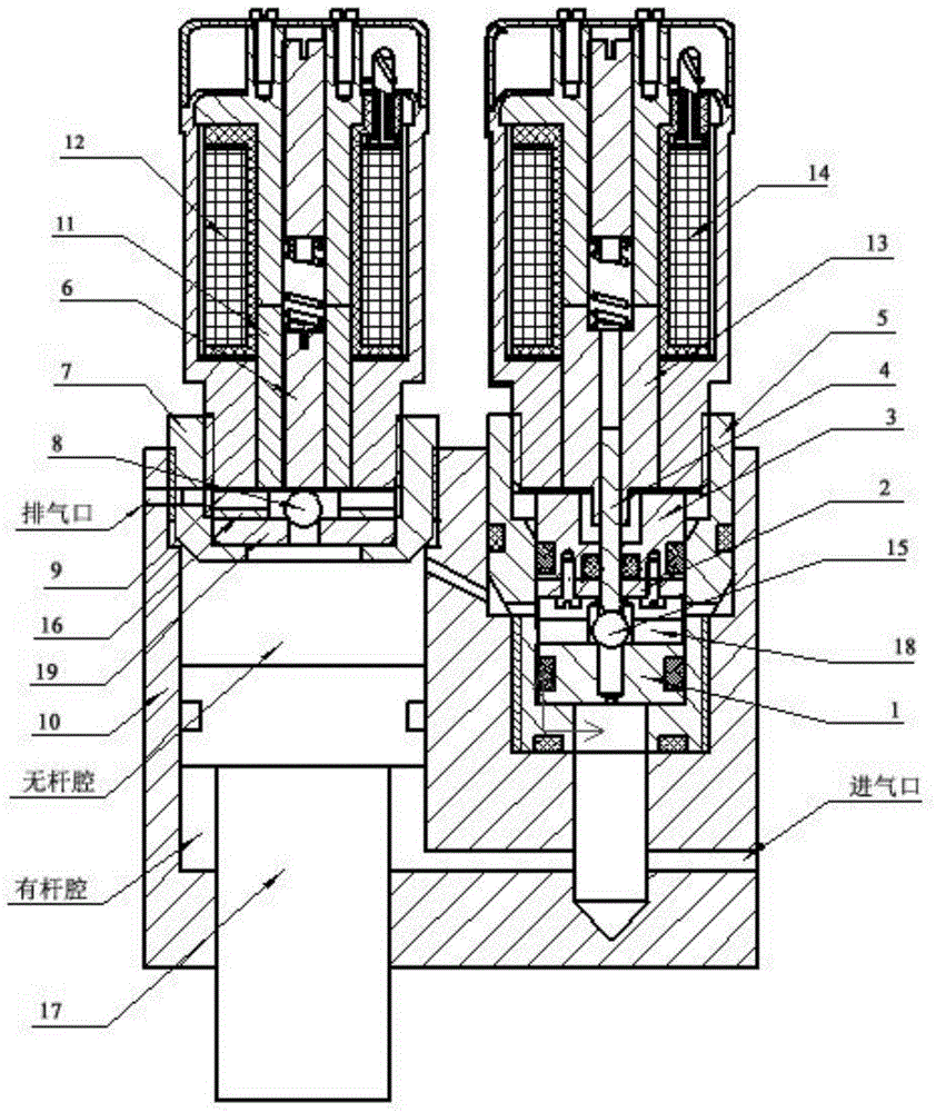
[0028] as attached figure 1 As shown, the present invention provides a plug-in pneumatic high-speed differential switch valve, the differential switch valve includes a valve seat 10, a piston 17, a cartridge valve assembly A and a cartridge valve assembly B, and the cartridge valve assembly B adopts The structure is different from the cartridge valve assembly A, which adopts the armature magnetic material and the valve core needle rod on it to form a whole to control the opening and closing of the spherical valve core.

[0029] The left half of the upper end surface of the valve seat 10 is processed with a step hole for installing the direct mounting valve assembly B, and the bottom surface of the step hole is processed with a through hole for installing the piston 17. The inner surface of the step hole above the step surface is processed with an internal ...


PUM


Abstract

The invention provides a plug-in type pneumatic high-speed differential switch valve which comprises a valve base, a piston, a plug-in valve component A and a plug-in valve component B, wherein when the plug-in valve component A works, under the suction effect of an electromagnet A, a valve core needle bar and a ball core A move upwards and are kept away from an exhaust duct, namely, high-pressure gas passes through a through hole of a valve core base, a vent hole of a supporting base and the vent hole of a plug-in valve sleeve A in turn, the gas flows into a step hole of the valve base from the vent hole of the step hole on the valve base, and the piston is kept static when the gas pressures in a rod cavity and a rod-less cavity are identical to each other. Under the effect of a pulse current and the suction effect of an electromagnet B, a valve core B is kept away from the exhaust duct, the high-pressure gas passes through the through hole of a plug-in valve sleeve B and the vent hole of a supporting ring in turn, namely, the gas in the rod-less cavity is drained to an exhaust port, so that the differential ratio control for the rod cavity and the rod-less cavity is formed. The plug-in type pneumatic high-speed differential switch valve is characterized in that the increasing of differential control response is realized, the working efficiency is high, the sealing property is high and the modularization for different structure groups is realized according to the characteristics of the differential control.

Description

technical field [0001] The invention relates to an on-off valve, in particular to a plug-in pneumatic high-speed differential on-off valve, which is suitable for a pneumatic system that continuously outputs speed, pressure, position, etc., and belongs to the technical field of pneumatic system servo ratio. Background technique [0002] In the field of pneumatic servo proportional technology, it is necessary to perform servo adjustment on the output speed, pressure and position of the pneumatic actuator in proportion. In the classic pneumatic servo proportional system, the slide valve proportional element is used. Due to the elastic coefficient of the gas, the control quality of the pneumatic servo proportional system is far from the level of the hydraulic system. Therefore, in the pneumatic control system, it is controlled by a high-speed switching element. The improvement of quality and the progress of pulse width modulation have been developed rapidly in the past ten years...

Claims


Application Information

Patent Timeline
Patent Type & Authority Patents(China)
IPC IPC(8): F15B13/02
Inventor 焦让黄一鸣姚丰宜
Owner 焦让
Why Eureka
Try Eureka