Electric water heater drain valve and electric water heater

A technology for electric water heaters and drain valves, applied to fluid heaters, valve details, valve devices, etc., can solve the problems of inconvenient and bulky after-sales maintenance, achieve the effect of beautiful appearance, beautiful appearance, and reduce procurement costs

Active Publication Date: 2014-08-13
广东新威博电器有限公司
View PDF6 Cites 3 Cited by
  • Summary
  • Abstract
  • Description
  • Claims
  • Application Information

AI Technical Summary

Problems solved by technology

When maintenance and replacement is required, the blowdown valve (such as a ball valve) must be removed, and then the water liner and the magnesium rod must be taken out from the blowdown hole of the inner tank. However, the blowdown valve used in existing electric water heaters has a relatively large valve body 1. The handle seat on the valve body protrudes outward, so that the maximum radial dimension of the blowdown valve often exceeds the size of the disassembly and assembly operation cavity reserved on the blowdown outlet of the electric water heater shell. Special tools bring inconvenience to after-sales maintenance

Method used


Image

  • Electric water heater drain valve and electric water heater
  • Electric water heater drain valve and electric water heater
  • Electric water heater drain valve and electric water heater

Examples


Embodiment Construction

[0020] The present invention will be further described below in conjunction with the accompanying drawings.

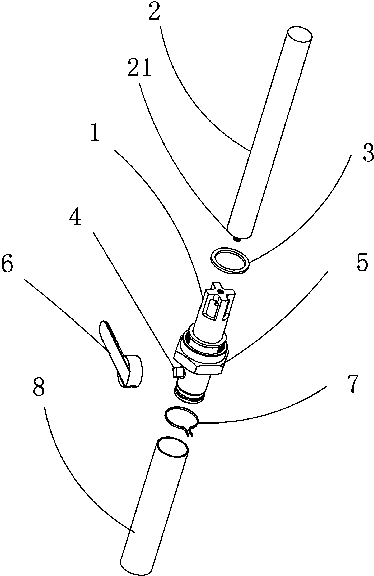
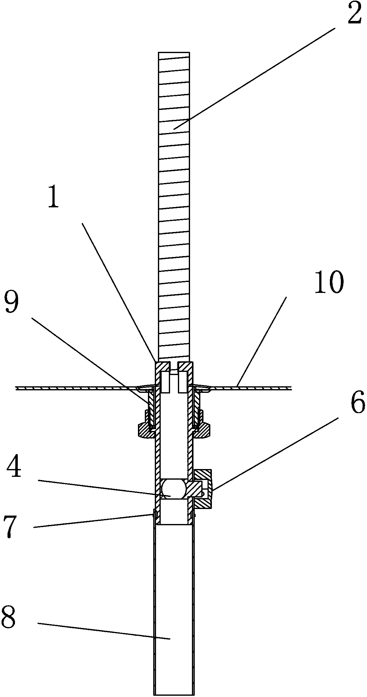
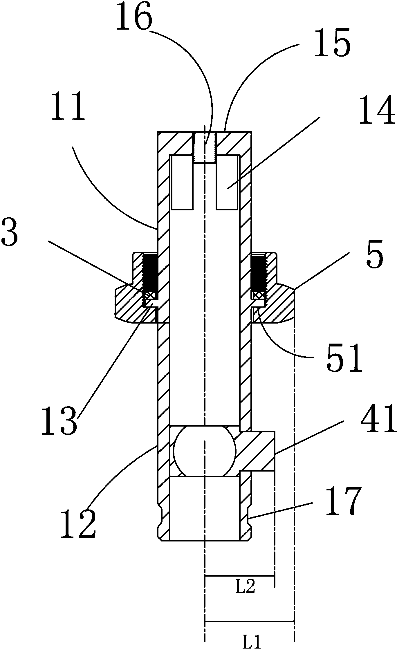
[0021] The electric water heater described in the present invention is a water storage type water heater, including an inner tank, an electric heating tube assembly, a water inlet pipe, a water outlet pipe and other components. The bottom of the inner tank of the water heater is provided with a pipe hole for the inlet and outlet pipes, and a sewage outlet , see figure 2 , A pipe joint is welded on the sewage outlet, and the electric water heater drain valve of the present invention is installed on the pipe joint. see Figure 1-3 , the electric water heater drain valve of the present invention is arranged at the bottom of the inner container of the electric water heater, and includes a valve body 1, a valve cavity, a valve core 4, and a handle switch 6. The valve body 1 includes a first valve portion 11 extending upward to the inner container, The second valve part 1...


PUM


Abstract

The invention discloses an electric water heater drain valve which is arranged at the bottom of an electric water heater inner container. The electric water heater drain valve comprises a valve body, a valve cavity, a valve element and a handle switch. The valve body comprises a first valve part which extends upwards into the inner container and a second valve part containing the valve element. The first valve part penetrates through a pipe connector at the bottom of the inner container and extends into the inner container. A water through groove is formed in the wall body of the end of the first valve part. A locating flange is arranged on the outer wall of the first valve part. A pressing nut is arranged below the locating flange in a sleeved mode. A pressing ring of the pressing nut is pressed on the locating flange. The inner threads of the pressing nut are matched with the outer threads on the outer side of the locating flange and are matched with the outer threads of the pipe connector at the bottom of the inner container. An opening is formed in the wall body of the second valve part. An adjusting rod part of the valve element extends out of the opening and is movably connected with the handle switch in a detachable mode. The outer diameter of the pressing nut is larger than the distance between the outer edge of the valve element adjusting rod part and the center axis of the valve cavity. Mounting and disassembling of a blow-down valve can be completed through a universal tool, and a valve mounting structure is in order and normalized.

Description

technical field [0001] The invention relates to the technical field of electric water heaters, and more specifically relates to a drain valve of the electric water heater and the electric water heater. Background technique [0002] In order to protect the inner tank and heating pipe of the electric water heater, most of the existing water storage electric water heaters are equipped with magnesium rods in the inner tank. According to the principle of sacrificial anode protection, the magnesium rod can replace the inner tank to undergo oxidation reaction, thereby protecting the Gallbladder is not corroded. Normal products have their rated service life. The service life of the magnesium rod depends on its size and the corrosive strength of the corrosive medium. In places with poor water quality, the water heater needs to be replaced after about one year of use. [0003] Magnesium rods are generally installed on the drain outlet of the inner tank of the electric water heater, a...

Claims


Application Information

Patent Timeline
Patent Type & Authority Applications(China)
IPC IPC(8): F16K27/06F16K5/00
CPCF16K27/06F24H9/2021
Inventor 欧永源吴宇翔谢德伟董越周志铭
Owner 广东新威博电器有限公司
Why Eureka
Try Eureka