Micro-nano optical fiber micro experiment structure, manufacturing method thereof and measuring instrument

A micro-nano fiber and measuring instrument technology, which is applied to cladding fibers, using optical devices to transmit sensing components, optical waveguides and light guides, etc. , stable practical application, easy processing effect

Active Publication Date: 2014-08-13
THE HONG KONG POLYTECHNIC UNIV SHENZHEN RES INST
View PDF5 Cites 15 Cited by
  • Summary
  • Abstract
  • Description
  • Claims
  • Application Information

AI Technical Summary

Problems solved by technology

[0005] The purpose of the present invention is to provide a micro-experimental structure of micro-nano optical fiber, aiming to solve the problem that dust particles and water vapor will affect the surface of micro-nano optical fiber in the prior art, causing the optical performance of micro-nano optical fiber to fade quickly with time

Method used


Image

  • Micro-nano optical fiber micro experiment structure, manufacturing method thereof and measuring instrument
  • Micro-nano optical fiber micro experiment structure, manufacturing method thereof and measuring instrument
  • Micro-nano optical fiber micro experiment structure, manufacturing method thereof and measuring instrument

Examples


Embodiment Construction

[0027] In order to make the object, technical solution and advantages of the present invention clearer, the present invention will be further described in detail below in conjunction with the accompanying drawings and embodiments. It should be understood that the specific embodiments described here are only used to explain the present invention, not to limit the present invention.

[0028] The implementation of the present invention will be described in detail below in conjunction with specific embodiments.

[0029] refer to Figure 1-13 Shown is the preferred embodiment provided by the present invention.

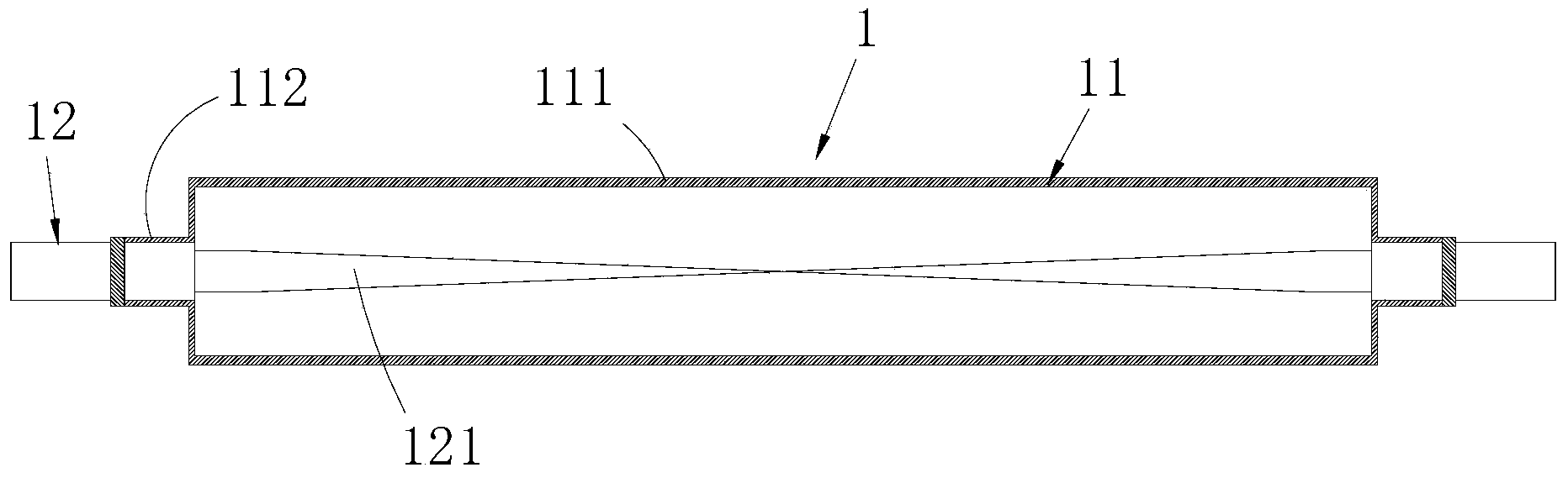
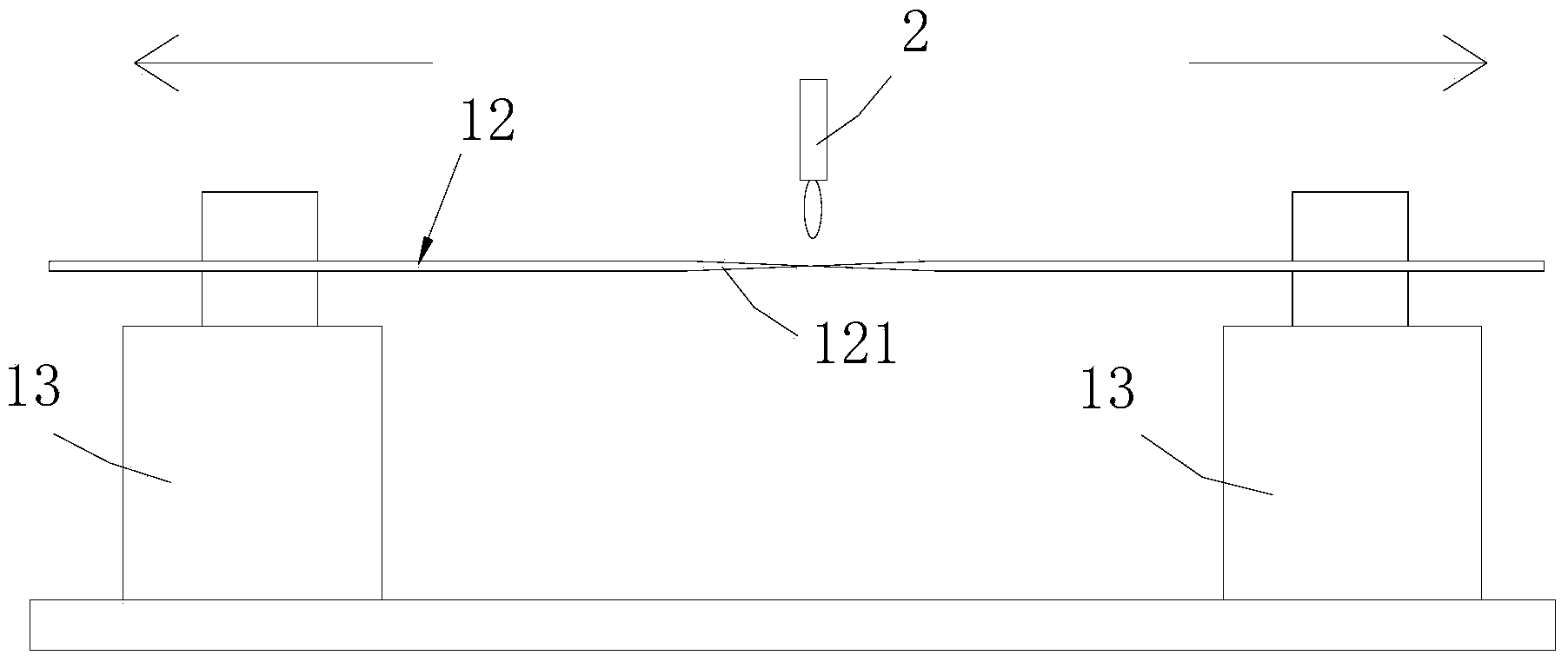
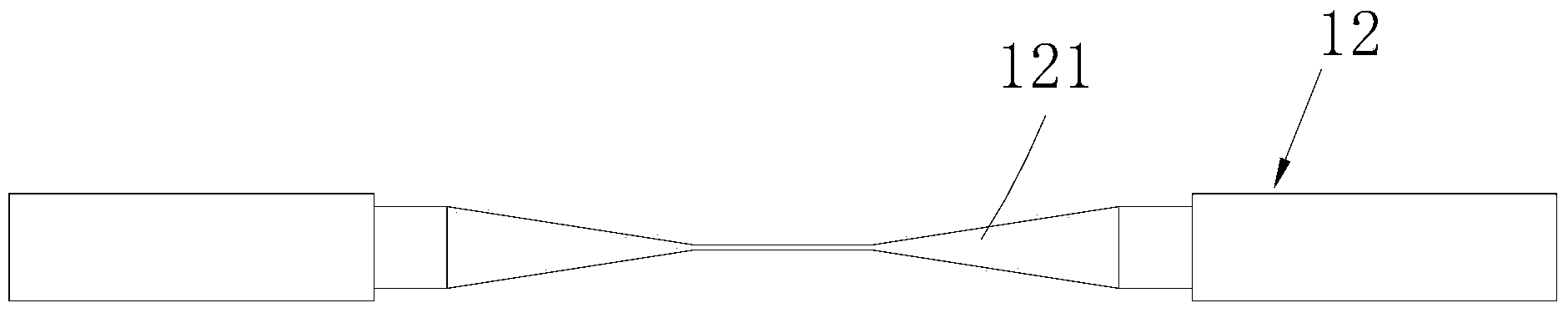
[0030] The micro-nano optical fiber micro-experimental structure 1 provided in this embodiment comprises a single-mode optical fiber 12 and a capillary glass straight tube 11, and the two ends of the capillary glass straight tube 11 have ports communicating with the inside thereof respectively; In the tube 11, the coating layer on it is fixedly connected to the port of th...


PUM


Abstract

The invention relates to the technical field of micro-nano optical fiber, and discloses a micro-nano optical fiber micro experiment structure, manufacturing method of the structure and measuring instrument. The micro experiment structure comprises monomode optical fiber and a capillary glass straight pipe, and ports are formed in the two ends of the capillary glass straight pipe; the middle of the monomode optical fiber is provided with drawing-made micro-nano optical fiber, the monomode optical fiber is arranged in the capillary glass straight pipe in a penetrated mode, and is fixedly connected with the capillary glass straight pipe, and the whole micro-nano optical fiber is arranged in the capillary glass straight pipe and is arranged in a suspended mode. Because the whole micro-nano optical fiber is arranged in the capillary glass straight pipe and is arranged in a suspended mode, under the protection of the capillary glass straight pipe, the micro-nano optical fiber is protected from being polluted, outside dust and vapor are avoided from making contact with the micro-nano optical fiber, optical nature of the micro-nano optical fiber will not be affected, the optical performance of the micro-nano optical fiber will not degrade rapidly along with time, the micro-nano optical fiber is easy to process, long-term and stable practical application of the micro-nano optical fiber can be achieved, and the micro-nano optical fiber is easy to compile with other optical fiber devices.

Description

technical field [0001] The invention relates to the technical field of micro-nano optical fiber, in particular to a micro-experimental structure of micro-nano optical fiber, a manufacturing method and a measuring instrument. Background technique [0002] Micro-nano fibers have received more and more attention due to their huge potential applications in micro-nano photonic systems. With the development trend of miniaturization and integration of photonic devices, various electronic devices based on micro-nano fibers have appeared. Moreover, due to the strong evanescent field of micro-nano fibers, they have a strong interaction with the outside world. , can better perceive changes in the external environment, thus, micro-nano optical fiber is widely used to realize various types of micro-nano optical fiber chemical, biological and environmental sensors. [0003] However, when dust particles are adsorbed on the surface of the micro-nano fiber, it will cause light scattering on...

Claims


Application Information

Patent Timeline
Patent Type & Authority Applications(China)
IPC IPC(8): G01M11/02G02B6/02G01D5/353
Inventor 靳伟金娃宣海锋汪超
Owner THE HONG KONG POLYTECHNIC UNIV SHENZHEN RES INST
Why Eureka
Try Eureka