Optical switch array and non-holographic real naked eye 3D display system formed from the same

An optical switch array and optical switch technology, applied in the field of 3D display, can solve the problems of low light utilization, eye fatigue, poor picture clarity and brightness, etc., and achieve high light source utilization, clear and real pictures, and convenient function expansion. Effect

Inactive Publication Date: 2014-08-13
JILIN UNIV
View PDF6 Cites 5 Cited by
  • Summary
  • Abstract
  • Description
  • Claims
  • Application Information

AI Technical Summary

Problems solved by technology

Most of the auxiliary equipment type needs to wear glasses, so it brings great inconvenience, high cost, and low light utilization rate. In addition, the naked eye type often causes eye fatigue, poor image quality, poor picture clarity and brightness, and limited viewing angle. limit and other issues
In addition, there is a volumetric 3D display method. This method is projected on a high-speed rotating screen, which has a scattering effect, and the image near the center is not clear. The high-speed rotating parts have problems such as noise and loss, and it is easy to bring danger.
[0003] To sum up, the current 3D display methods have great defects and cannot represent the maturity level of 3D display technology.

Method used


Image

  • Optical switch array and non-holographic real naked eye 3D display system formed from the same
  • Optical switch array and non-holographic real naked eye 3D display system formed from the same
  • Optical switch array and non-holographic real naked eye 3D display system formed from the same

Examples


Embodiment 1

[0029] Embodiment 1 Embodiment of "T" shaped optical switch

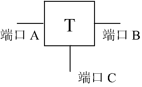
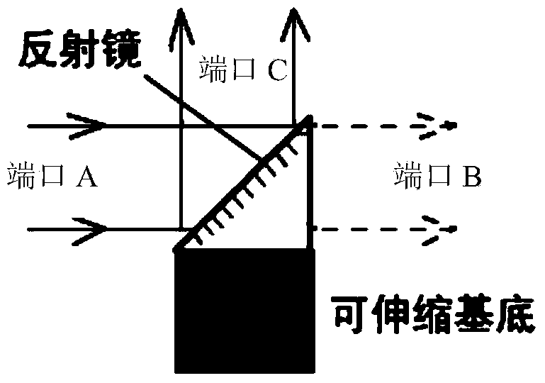
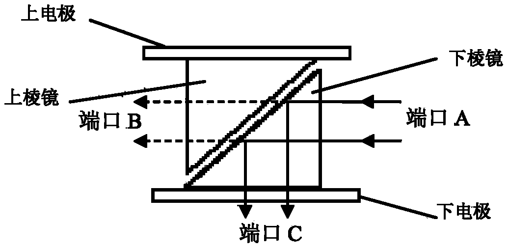
[0030] Please refer to figure 1 , 2 , 3, figure 1 The structure and function of the "T" shaped optical switch are shown. It has three ports. Port A and port B are on the same straight line. The direction of port C is perpendicular to the straight line where port A and port B are located. This optical switch has optical path conversion Function, the light entering from port A can be controlled to choose to exit from port B or port C; figure 2 , 3 It is the concrete embodiment of two kinds of micromechanical "T" shaped optical switches.

[0031] figure 2 The "T"-shaped optical switch is mainly composed of a stretchable base and a reflector. The stretchable base can be composed of an electromagnet and an armature sandwiching an elastic material. The reflector is fixed on the armature, so that by controlling the electrical signal applied to the base The state of the optical switch can be controlled: when the coi...

Embodiment 2

[0034] Embodiment 2 "T" shape optical switch array embodiment

[0035] Please refer to figure 1 and Figure 4 , the optical switch array is composed of multiple figure 1 The "T" shaped optical switch shown is formed by combining connections. figure 1 A plurality of such "T" optical switches (the lower limit is 1 and the upper limit is not limited) are connected in sequence, and the port B of the first "T" optical switch is connected to the port A of the second "T" optical switch. The port B of the second "T" shaped optical switch is connected to the port A of the third "T" shaped optical switch, and so on, and the ports C of all "T" shaped optical switches point to the same direction, so that Form an optical switch chain. In the three-dimensional rectangular space coordinates, one optical switch chain is placed along the y-axis. For the convenience of expression, it is called the y-chain. Any number of optical switch chains is placed along the z-axis. For the convenience o...

Embodiment 3

[0036] Embodiment 3 Stereoscopic display unit embodiment

[0037] Please refer to Figure 5 , Figure 5 The schematic diagram of the stereoscopic display unit is shown. According to the convex lens imaging formula, the light point on the optical switch array 12 is used as the object point, and an image point can be formed after passing through the lens module 15 . When the optical switch array 12 is at a certain fixed position, the image point can be scanned two-dimensionally on a fixed image plane by row scanning and column scanning of the optical switches on the optical switch array 12; now the translation driver 11 is used to drive the optical switch The array 12 moves in a direction perpendicular to the optical switch array (depth-of-field scanning). Combining with the two-dimensional scanning of the optical switch array 12 itself, the image points can be scanned in three-dimensional space, thereby achieving the effect of 3D display. It should be noted that, in order to ...


PUM


Abstract

The invention relates to an optical switch array and a non-holographic real naked eye 3D display system formed from the same. The optical switch array comprises an optical switch chain which is arranged in the y axis in a three-dimensional rectangular coordinate system and a plurality of T-shaped optical switch chains which are arranged in parallel to the z axis. The non-holographic real naked eye 3D display system structure comprises a display array (1) formed by jointing three-dimensional display units, a drive module (2) and a processor (3). The control of each T-shaped optical switch in the three-dimensional display units are connected with the drive module (2). The drive module (2) and a translation driver(11) and a display light source (14) in each three-dimensional display units are all connected with the processor (3). A three-dimensional image is formed in space through the scanning manner to realize real naked eye 3D display. According to the invention, advantages of simple structure, low operation power consumption and long service life can be realized, the display colour gamut is equivalent to a laser television, and the advantage of naked eye watching can be realized; the screen size is flexible, so needs in different occasions can be satisfied; and the advantage of 2D and 3D compatibility can be realized.

Description

technical field [0001] The invention belongs to the technical field of 3D display, and relates to a 3D display method, in particular to an optical switch array and a non-holographic real naked-eye 3D display system composed of the same. Background technique [0002] 3D display technology is a new generation of display technology that can express depth of field. At present, the main 3D display technology is to use a series of optical methods to make people's left and right eyes produce parallax to receive different pictures, and form a 3D (3Dimensions) stereoscopic effect in the brain. There are many technical solutions for realizing 3D display, which can be generally divided into two categories according to the display principle: holographic and non-holographic. Among them, the holographic method is a technology that forms a real 3D image in a 3D space. This method is very difficult technically, and there are still a series of problems that have not been solved. It is diffi...

Claims


Application Information

Patent Timeline
Patent Type & Authority Applications(China)
IPC IPC(8): G02B26/08G02B27/22
Inventor 王广军龙国徽吴香英纪媛庞明俊汪东雪罗阳
Owner JILIN UNIV
Why Eureka
Try Eureka