A contact structure and method for eliminating closing bounce

A closing bounce and contact technology is applied in the fields of detailed information of electromagnetic relays, electrical components, electromagnetic relays, etc. It can solve the problems that it is difficult to achieve no bounce of contacts, meet the requirements of reducing material performance and processing accuracy, eliminate bounce, Avoid the rebound effect

Active Publication Date: 2015-12-30
STATE GRID CORP OF CHINA +3
View PDF5 Cites 0 Cited by
  • Summary
  • Abstract
  • Description
  • Claims
  • Application Information

AI Technical Summary

Problems solved by technology

[0005] This requires the use of alloy materials with excellent performance, complex mechanism design, and high-precision processing, installation and debugging, and can only continuously enhance the suppression effect on contact bounce, and it is difficult to achieve complete contact no bounce

Method used


Image

  • A contact structure and method for eliminating closing bounce
  • A contact structure and method for eliminating closing bounce
  • A contact structure and method for eliminating closing bounce

Examples


Embodiment 1

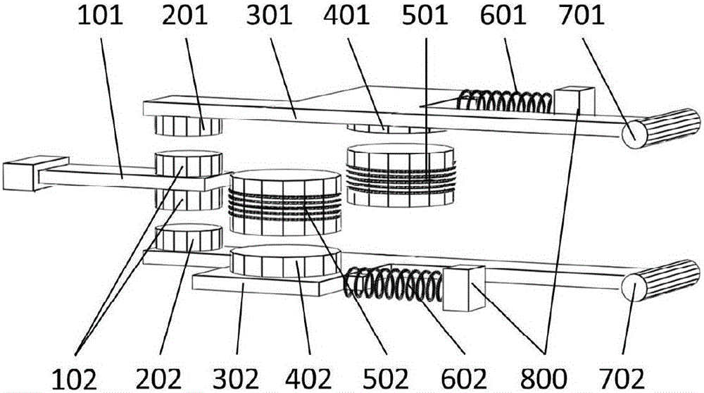
[0027] The closure of the contact structure in the present invention:

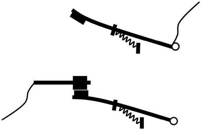
[0028] 1. The two ends of the grid line are respectively connected to the upper moving contact and the static contact, and the initial state is the line disconnected state, such as figure 2 As shown, the upper moving contact is separated from the static contact, and the lower moving contact is closed to the static contact;

[0029] 2. The first electromagnetic coil (501) is energized to generate a magnetic field, and the magnetic field attracts downward the first permanent magnet (401) fixed on the upper moving contact, and the upper moving contact moves downward against the force of the compression spring;

[0030] 3. When the first moving contact (201) at the front end of the upper moving contact collides with the fixed contact (102), an impact is generated instantly, and the impulse of the upper moving contact is transferred to the lower moving contact. A spring (601) maintains reliable contact with t...

Embodiment 2

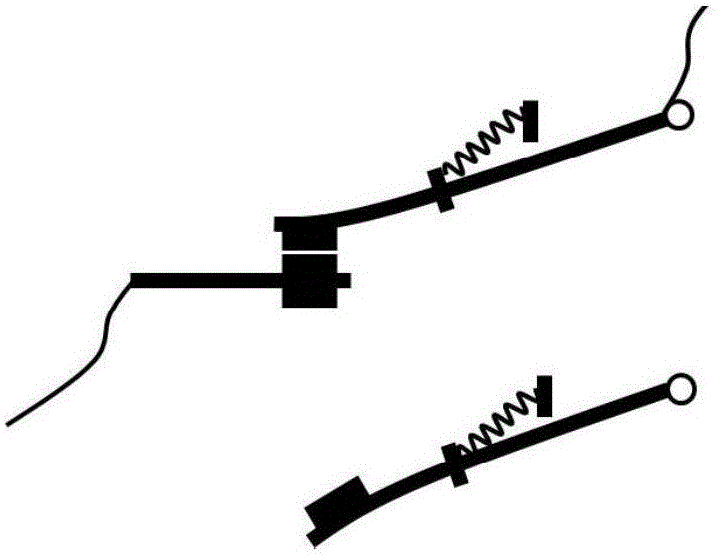
[0033] Disconnection of the contact structure in the present invention:

[0034] 1. The closed state of the line is as follows: image 3 As shown, the upper moving contact is connected to the static contact, and the lower moving contact is disconnected from the static contact;

[0035] 2. The first electromagnetic coil (501) is energized in reverse to generate a magnetic field, and the magnetic field generates an upward repulsion force on the first permanent magnet (401) fixed on the upper moving contact, and the force on the upper moving contact overcomes the force of the compression spring and moves upward to match the static force. The contacts separate and the grid line is disconnected.

[0036] 3. The second electromagnetic coil (502) is energized at the same time to generate a magnetic field, and the magnetic field generates an upward attractive force on the second permanent magnet (402) fixed on the lower moving contact. The static contact is closed.

[0037] From th...


PUM


Abstract

The invention discloses a contact structure and method for eliminating closing bounce, and pertains to the technical field of power electronics. The contact structure comprises an upper moving contact, a fixed contact, a lower moving contact, a first electromagnetic coil (501), a second electromagnetic coil (502), a first spring (601), a second spring (602), and a device shell (800). Grid line connection and disconnection are realized through the contact structure. Two ends of a grid line are connected onto the upper moving contact and the fixed contact separately. When the line is disconnected, the upper moving contact is separated from the fixed contact, and the lower moving contact and the fixed contact are closed. The upper moving contact is moved downwards under the action of the electromagnetic coil (501), and when the upper moving contact and the fixed contact are in collision, the impulse is transferred downwards, and the upper moving contact bounce can be eliminated through impulse transfer. The impulse is obtained by the lower moving contact so as to be bounced out and separated from the fixed contact. The impact energy is consumed by the second spring (602) finally. The upper moving contact is maintained to be in reliable contact with the fixed contact under the action of the first spring (601) to realize grid line connection.

Description

technical field [0001] The invention relates to a contact structure and method for eliminating closing bounce, belonging to the technical field of power electronics. Background technique [0002] The contact structure is a basic component of switching devices commonly used in power systems such as relays and circuit breakers. The traditional contact structure has the closing bounce phenomenon. When the switching device performs the closing operation, the moving contact and the static contact will be pushed away by the reaction force for many times after they collide with the static contact, and then they will be pushed away again. Severe cases bounce repeatedly 4 to 5 times, and the process lasts for 2 to 10 ms. [0003] Closing bouncing affects the quality of power supply. The bouncing phenomenon of the contacts when the switching device is closing will generate an operating overvoltage, sometimes as high as 5 times the applied voltage, causing great damage to the power eq...

Claims


Application Information

Patent Timeline
Patent Type & Authority Patents(China)
IPC IPC(8): H01H50/58
Inventor 张怡
Owner STATE GRID CORP OF CHINA
Why Eureka
Try Eureka