Multi-region drive inertia piezoelectric motor device, scanning probe microscope and control method

A technology of piezoelectric motors and drive circuits, applied in the direction of scanning probe technology, piezoelectric effect/electrostrictive or magnetostrictive motors, electrical components, etc., can solve the problem of small thrust, so as to improve thrust and avoid driving The effect of the circuit

Active Publication Date: 2014-08-13
UNIV OF SCI & TECH OF CHINA
View PDF5 Cites 14 Cited by
  • Summary
  • Abstract
  • Description
  • Claims
  • Application Information

AI Technical Summary

Problems solved by technology

[0004] In order to solve the shortcoming of low thrust of the existing inertial piezoelectric motor, a multi-zone driven inertial piezoelectric motor device, its control method, a scanning probe microscope made of it and a rough approximation method for the scanning probe microscope are provided

Method used


Image

  • Multi-region drive inertia piezoelectric motor device, scanning probe microscope and control method
  • Multi-region drive inertia piezoelectric motor device, scanning probe microscope and control method
  • Multi-region drive inertia piezoelectric motor device, scanning probe microscope and control method

Examples


Embodiment 1

[0024] Example 1: Basic multi-zone driven inertial piezoelectric motor device

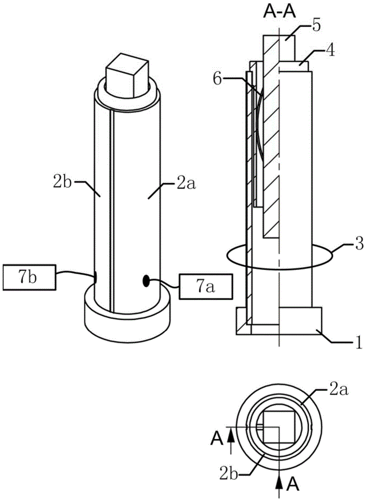
[0025] See attached figure 1 , an inertial piezoelectric motor device driven by multiple zones, including a slider 5, a base 1, a spring leaf 6, and a guide rail 4, and is characterized in that it also includes two or more piezoelectric bodies, and the piezoelectric bodies are deformed according to The structure with the same direction and independently applied voltage is fixed together to form a piezoelectric body group 3, one end of the piezoelectric body group 3 is fixed on the base, and the other end is a free deformation end, and the guide rail 4 is fixed on the free deformation end , it moves with the extension of the piezoelectric body, and its guiding direction is consistent with the deformation direction of the piezoelectric body group 3, and the spring piece 6 applies a positive pressure perpendicular to the deformation direction of the piezoelectric body group 3 to slide The block 5 is ...

Embodiment 2

[0027] Embodiment 2: Inertial piezoelectric motor device with integrated multi-zone drive

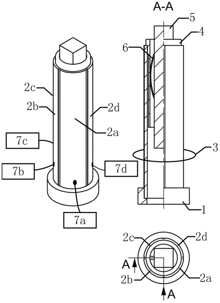
[0028] The piezoelectric bodies in the piezoelectric body group 3 in the above embodiments may be integrated. This simplifies the structure and manufacture of the present invention.

Embodiment 3

[0029] Embodiment 3: Inertial piezoelectric motor device driven by tubular multi-zones

[0030] The piezoelectric body group 3 in the above embodiments may be tubular. This results in an improved symmetry of the invention, thereby reducing asymmetry-induced drift.


PUM


Abstract

The invention relates to a multi-region drive inertia piezoelectric motor device, a scanning probe microscope and a control method. The inertia piezoelectric motor device comprises a sliding block, a base, a spring piece, a guide rail and two or more piezoelectrics. The scanning probe microscope formed by the multi-region drive inertia piezoelectric motor device comprises a support additionally arranged, the support is fixed to the base, and a part of the support is over against the guiding direction of the guide rail. The control method of the multi-region drive inertia piezoelectric motor device includes the step that inertia piezoelectric motor drive circuits arranged on all the piezoelectrics in a piezoelectric group synchronously output inertia piezoelectric motor drive signals for homodromous pushing; the coarse approach control method of the scanning probe microscope includes the step that special inertia piezoelectric motor drive circuits arranged on all the piezoelectrics in the piezoelectric group synchronously output inertia piezoelectric motor drive signals for homodromous pushing.

Description

technical field [0001] The present invention relates to a piezoelectric motor device, in particular to a multi-zone driven inertial piezoelectric motor device, its control method, a scanning probe microscope made of it and a rough approximation method for the scanning probe microscope, belonging to piezoelectric Electric positioner technical field. Background technique [0002] The piezoelectric motor is a piezoelectric positioner that can accumulate the microscopic small piezoelectric displacement generated by each step into a macroscopic large displacement. Large), thus becoming a powerful positioning tool for today's precision measurement, nano-device processing, atomic and molecular manipulation, and even subatomic structure imaging. Its current development trend is high rigidity, high thrust, and miniaturization. The inertial piezoelectric motor uses the inertial force generated by the sudden deformation of the piezoelectric body to overcome the friction acting on the...

Claims


Application Information

Patent Timeline
Patent Type & Authority Applications(China)
IPC IPC(8): H02N2/02H02N2/06G01Q10/02
Inventor 周海彪陆轻铀
Owner UNIV OF SCI & TECH OF CHINA
Why Eureka
Try Eureka