
Dual-frequency band radiofrequency power amplifier impedance match circuit

An amplifier impedance and matching circuit technology, applied in the field of matching circuits, can solve the problems of large occupied area, high cost, complex circuit, etc., and achieve the effect of simple structure and low cost

Inactive Publication Date: 2014-08-13
TIANJIN UNIV
View PDF2 Cites 17 Cited by
  • Summary
  • Abstract
  • Description
  • Claims
  • Application Information

AI Technical Summary

Problems solved by technology

Usually, switching multiple power amplifiers through switches, or using power amplifiers with reconfigurable structures, is the best circuit solution for the optimal design of each frequency band, but these structures can only work in one frequency band at a certain time , it is difficult to achieve the requirement of working in multiple frequency bands at the same time, and it also has the disadvantages of large footprint, complex circuit and high cost

Method used


Image

  • Dual-frequency band radiofrequency power amplifier impedance match circuit
  • Dual-frequency band radiofrequency power amplifier impedance match circuit
  • Dual-frequency band radiofrequency power amplifier impedance match circuit

Examples


Embodiment Construction

[0016] The technical solutions of the present invention will be further described in detail below in conjunction with the accompanying drawings and specific embodiments.

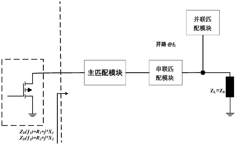
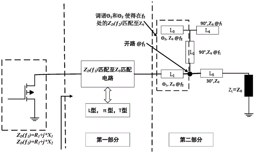
[0017] Such as figure 1 As shown, a dual-band radio frequency power amplifier impedance matching circuit of the present invention is composed of a full microstrip structure arranged between the radio frequency source and the load, and in the signal path flowing from the radio frequency source to the load, the full microstrip structure consists of three It consists of two matching modules, including a main matching module and a series matching module connected in series in the signal path of the radio frequency microwave signal, and a parallel matching module is connected between the series matching module and the load; through reasonable design of the structure of each module, it can be simultaneously Impedance matching of the two frequency bands is achieved.

[0018] The series matching module is the chara...


PUM


Abstract

The invention discloses a dual-frequency band radiofrequency power amplifier impedance match circuit, which is formed by a full microband structure arranged between a radiofrequency source and a load; the full microband structure comprises a main match module and a serial match module which are sequentially serially connected in a signal path of a radiofrequency microwave signal; a parallel match module is connected between the serial match module and the load in parallel; the serial match module is a transmission wire of which the characteristic impedance Z0 and the load impedance ZL are same; when at a first frequency f1, the main match module realizes that the first frequency impedance is matched to the load impedance and the match of the main match module at the f1 is not influenced by the serial match module and the parallel match module. When at a second frequency f2, the impedance match can be performed by the serial match module and the parallel match module. The impedance match of two frequency bands can be realized by reasonably designing the structure of each module, so the work demand on multiple frequency bands is realized.

Description

technical field [0001] The invention belongs to the technical field of wireless communication, and in particular relates to a matching circuit capable of simultaneously performing impedance matching on radio frequency signals of two frequency bands in each frequency band. Background technique [0002] The rapid development of wireless communication technology and new wireless communication technology increasingly require that the communication transceiver must work in multiple frequency bands and support multiple communication standards at the same time, so as to achieve the purpose of reducing cost and size. For example, in each standard of IEEE [Institute of Electrical and Electronics Engineers, Institute of Electrical and Electronic Engineers] 802.11 a / b / g which is a wireless LAN [Local Area Network, Local Area Network 8 standard], the 5.2 GHz frequency band and the 2.4 GHz frequency band are specified. two frequency bands. [0003] The RF power amplifier is an essential...

Claims


Application Information

Patent Timeline
Patent Type & Authority Applications(China)
IPC IPC(8): H03F1/56H03F3/189
Inventor 马建国邬海峰成千福
Owner TIANJIN UNIV
Learn More