Cerebrospinal fluid drainage pressure limiter

A pressure limiter and cerebrospinal fluid technology, applied in wound drainage devices, suction devices, hypodermic injection devices, etc., can solve the problems of affecting the recovery of patients, reducing intracranial pressure, and endangering the lives of patients.

Active Publication Date: 2016-12-28
GENERAL HOSPITAL OF PLA
View PDF8 Cites 0 Cited by
  • Summary
  • Abstract
  • Description
  • Claims
  • Application Information

AI Technical Summary

Problems solved by technology

However, excessive loss of cerebrospinal fluid will lead to a decrease in intracranial pressure and headaches, which will affect the recovery of the patient. In severe cases, it will also lead to cerebellar sagging, that is, brain herniation, and even endanger the life of the patient.

Method used


Image

  • Cerebrospinal fluid drainage pressure limiter
  • Cerebrospinal fluid drainage pressure limiter
  • Cerebrospinal fluid drainage pressure limiter

Examples


Embodiment Construction

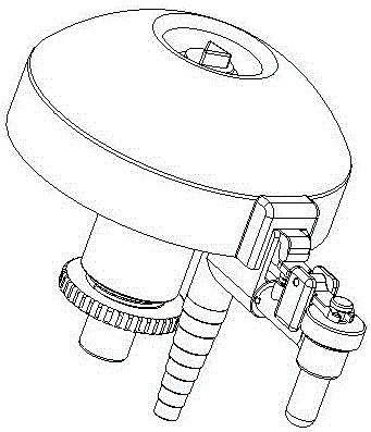
[0053] figure 1 Diagram of cerebrospinal fluid drainage pressure limiter.

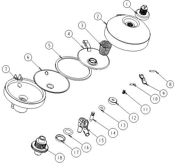
[0054] figure 2 The exploded view of the pressure limiter for cerebrospinal fluid drainage: including the pressure-limiting adjustment button (1), the upper cover of the pressure limiter (2), the return spring (3), the pressure-sensitive push plate (4), the upper diaphragm (5), and the valve Diaphragm (6), pressure limiter housing (7), outflow switch shaft (8), outflow switch pressure plate (9), pressure-sensitive push plate shaft (10), switch return spring (11), small O-shaped Ring fixing sleeve (12), small O-ring (13), outflow valve core (14), outflow valve body (15), pressure measuring O-ring (16), sealing O-ring (17), pressure measuring switch interface (18) Composition.

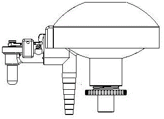
[0055] image 3 Front view of cerebrospinal fluid drainage pressure limiter

[0056] Figure 4 Top view of cerebrospinal fluid drainage pressure limiter

[0057] Figure 5 Cross-sectional direction of cerebrospinal fluid drainage pres...


PUM


Abstract

A cerebrospinal fluid drainage pressure limiter, which includes a pressure limiter adjustment button, a pressure limiter upper cover, a return spring, a pressure-sensitive push plate, a valve membrane upper piece, a valve membrane lower piece, a pressure limiter housing, an outflow switch shaft, Outflow switch pressure plate, pressure-sensitive push plate shaft, switch return spring, small O-ring fixed sleeve, small O-ring, outflow spool, outflow valve body, pressure measuring O-ring, sealing O-ring, measured pressure switch interface; the outflow valve body is provided with a three-way pipe, the three-way pipe has a liquid inlet, and the three-way pipe is respectively connected to the liquid outlet nozzle of the capsule, the pressure-tested switch interface, and the outflow valve core, wherein the capsule is composed of The lower valve membrane and the upper valve membrane are bonded together; when the pressure measuring switch interface and the outflow valve core are closed, the entering cerebrospinal fluid expands the capsule, pushes the pressure-sensitive push plate and the outflow switch pressure plate on it, and opens the outflow valve core The cerebrospinal fluid flows out; when the pressure of the cerebrospinal fluid is low, the capsule in the valve shrinks under the action of the return spring and the switch return spring, and the valve is closed.

Description

Technical field [0001] The invention relates to a device for drainage of cerebrospinal fluid after spinal surgery and for controlling the retained pressure value. Background technique [0002] Clinically, spinal surgery often requires an artificial incision of the dura. Some patients may tear the dura by mistake due to the adhesion of the dura to the surrounding tissues. These patients need indwelling drainage. Wound exudate enters the skull, reducing the risk of intracranial infection. However, excessive loss of cerebrospinal fluid can cause headaches in intracranial pressure reduction and affect the patient's recovery. In severe cases, it can also cause cerebellar prolapse, that is, cerebral herniation, and even endanger the patient's life. Therefore, a certain pressure must be maintained when the drainage tube is placed for drainage, usually between 80-180 mm water column. Summary of the invention [0003] The cerebrospinal fluid drainage pressure limiter is a product based o...

Claims


Application Information

Patent Timeline
Patent Type & Authority Patents(China)
IPC IPC(8): A61M1/00
CPCA61M1/00A61M27/006A61M1/73A61M1/74A61M39/22F16K7/14F16K15/14
Inventor 苏晓静郑国权胡智飞卢德华
Owner GENERAL HOSPITAL OF PLA
Why Eureka
Try Eureka