Retractable horizontal oil well packer

A technology for packers and oil wells, which is applied in sealing/isolation, wellbore/well parts, earthwork drilling and production, etc. It can solve the problems of hindering the recovery of rubber sleeves, input of manpower and material resources, and increase of oil production costs, etc., and achieve fracturing stuck Low well rate, improved oil production efficiency and long service life

Inactive Publication Date: 2014-08-20
翟灵光
View PDF0 Cites 1 Cited by
  • Summary
  • Abstract
  • Description
  • Claims
  • Application Information

AI Technical Summary

Problems solved by technology

There are many types of packers, most of which use rubber tubes to bulge and shrink, and there are also many structures for horizontal wells, but no matter what kind of packer is used in horizontal oil layers, the rubber tube cannot be restored to its original state
Because there is residual fracturing sand remaining during fracturing, which hinders the recovery of the rubber cartridge, especially because there is a circular bending section between the horizontal well and the vertical well, when lifting the fracturing string, due to friction and tension , so that the lifting force cannot be transmitted to multiple packers in the horizontal layer. If the fracturing string is not raised, the production string cannot enter, and crude oil cannot be produced from the oil well.
Also because the gap between the packer rubber sleeve and the casing wall is too small, the fracturing sticking rate is above 65%, and a large amount of high-pressure water is required to flush after the well is stuck, resulting in a large investment of manpower and material resources, and the cost of oil production is greatly increased. This issue is an urgent need for the oil industry

Method used


Image

  • Retractable horizontal oil well packer
  • Retractable horizontal oil well packer
  • Retractable horizontal oil well packer

Examples


Embodiment Construction

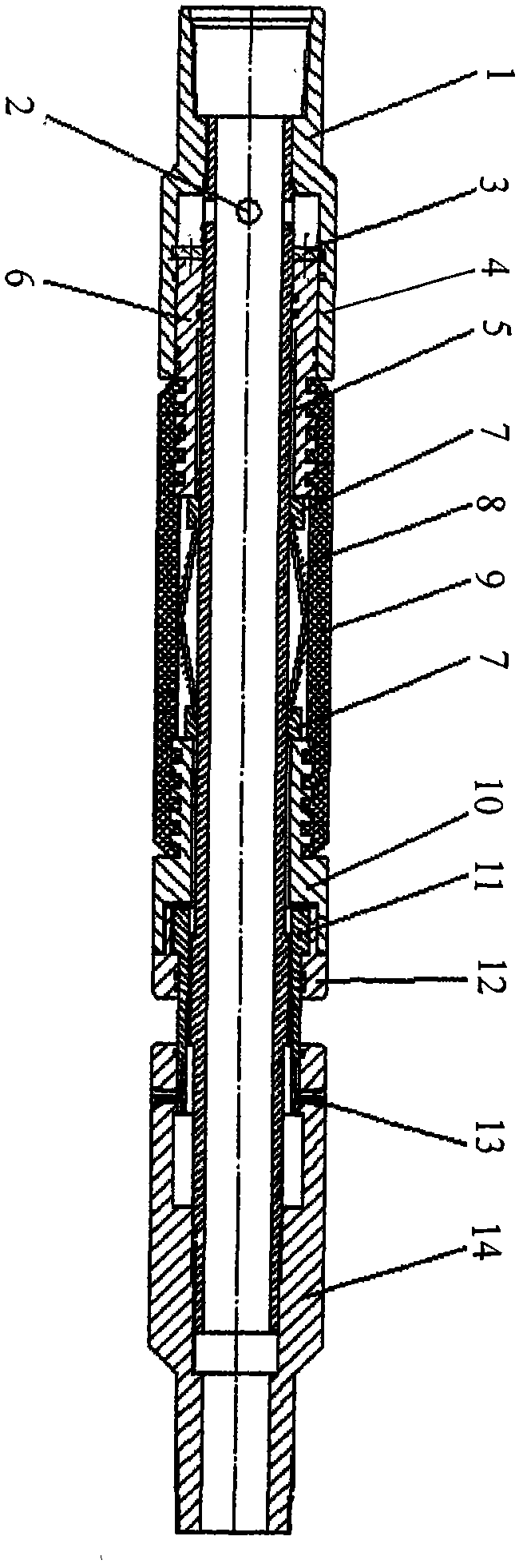
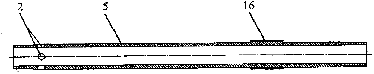
[0015] Depend on figure 1 , figure 2 It can be seen that the retractable horizontal oil well packer of the present invention includes a tubular left joint 1 and a right joint 14, wherein the right end of the left joint 1 is connected with the piston sleeve 4 as a whole, and the connection between the left joint 1 and the piston sleeve 4 It is coaxially connected with the left end of the central tube 5, and several liquid inlet holes 2 are arranged on the wall of the central tube 5 at the connecting end; on the outer diameter of the central tube 5, the sleeve piston 6 and the drum-shaped flower basket expansion tube are sequentially slid. , pulling seat 10 and rotating suit left-handed slider 11; the left end of the piston cylinder 6 is fitted with the piston sleeve 4 sliding plug seals, and the left end face of the piston cylinder 6 is equipped with a positioning jumper 3, and the jumper 3 is aligned radially with the piston The inner diameter of the sleeve 4 is equipped wit...


PUM


Abstract

A retractable horizontal oil well packer comprises a left joint and a right joint. The left joint is connected with a piston sleeve, the center of the left joint is fixedly communicated with a center tube, the wall of the center tube is provided with a liquid inlet hole, and the outer diameter of the liquid inlet hole is sequentially provided with a piston cylinder, a drum type basket extension cylinder and a pull base in a sliding and sleeved mode and is rotatably provided with a left rotation puller in a sleeved mode; the piston cylinder is matched with the piston sleeve in a sliding and sealed mode; the drum type basket extension cylinder is sleeved with a sealant cylinder, and the two ends of the sealant cylinder are connected with the piston cylinder and the pull base respectively; the left rotation puller and the pull base are assembled and then fixedly connected through a cover ring, the inner diameter of the end where the left rotation puller is connected with the pull base is movably connected with left rotation threads on the outer diameter of the center tube, the left rotation puller is arranged in the inner diameter of the right joint in a sliding and sleeved mode, a guide groove in the left rotation puller is matched with a guide column on the right joint in a sliding mode, and the center of the right joint is in threaded connection with the outer diameter of the center tube. By means of hydraulic pressure rising, the structure capable of rotating and retracting enables the extension spring type sealant cylinder to restore an initial state after pressure rising, the fracturing and well sticking rate is low, service life is long, and oil production efficiency is greatly improved.

Description

technical field [0001] The invention relates to an oil well packer, in particular to a device used in the fracturing process of the exploitation operation for having a horizontal oil layer. Background technique [0002] Due to the advancement of technology, oil wells are no longer completely vertical shafts. Modern drilling techniques have successfully drilled the oil layer horizontally, that is, vertical drilling above the oil layer, and horizontal drilling at the oil layer section. [0003] Fracturing is one of the necessary processes in oil extraction technology, because the oil layer needs to be cut into several layers through the fracturing process after the oil well has just been drilled, and the oil will penetrate into the casing along the cut gaps in large quantities, and then Use the pumping unit to drive the oil pump to pump out the oil; during the oil production process, it was found that the crude oil seeped out slowly, which was caused by the clogging of the cut...

Claims


Application Information

Patent Timeline
IPC IPC(8): E21B33/126
Inventor 翟灵光
Owner 翟灵光
Why Eureka
Try Eureka