
Automatic dust removal board type falling film generation device utilizing waste heat of exhaust gas

A flue gas waste heat generation device technology, applied in the direction of generator/analyzer, lighting and heating equipment, refrigeration components, etc., can solve the problem of increasing heat transfer resistance, reducing the heat transfer performance of falling film tubes, and affecting the overall performance of generators. Performance and other issues, to achieve the effect of preventing falling film dry pipe, enhancing liquid film disturbance, and increasing driving force

Active Publication Date: 2014-08-20
山东东岳能源交口肥美铝业有限责任公司
View PDF6 Cites 2 Cited by
  • Summary
  • Abstract
  • Description
  • Claims
  • Application Information

AI Technical Summary

Problems solved by technology

For the shell-and-tube falling film generator, the dust accumulation on the outer wall of the falling film tube, especially on the windward side, will seriously reduce the heat transfer performance of the falling film tube, increase the heat transfer resistance, and affect the overall performance of the generator.

Method used


Image

  • Automatic dust removal board type falling film generation device utilizing waste heat of exhaust gas
  • Automatic dust removal board type falling film generation device utilizing waste heat of exhaust gas
  • Automatic dust removal board type falling film generation device utilizing waste heat of exhaust gas

Examples


Embodiment Construction

[0026] The technical solution of the present invention will be described in detail below in conjunction with the accompanying drawings.

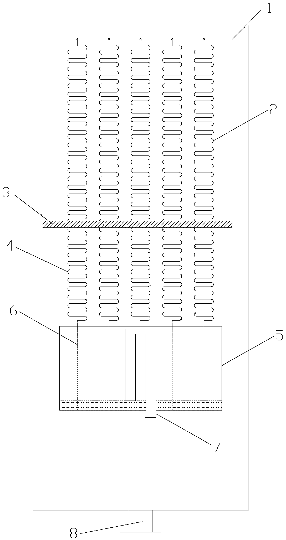
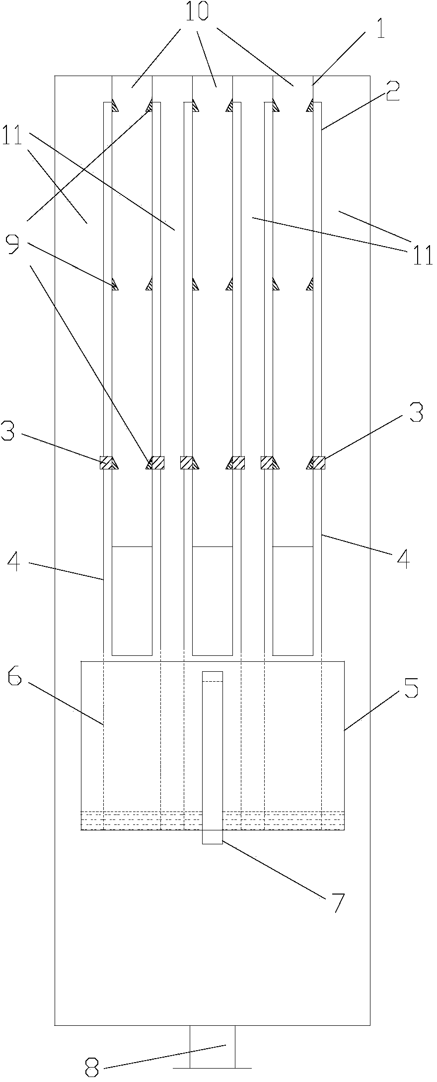
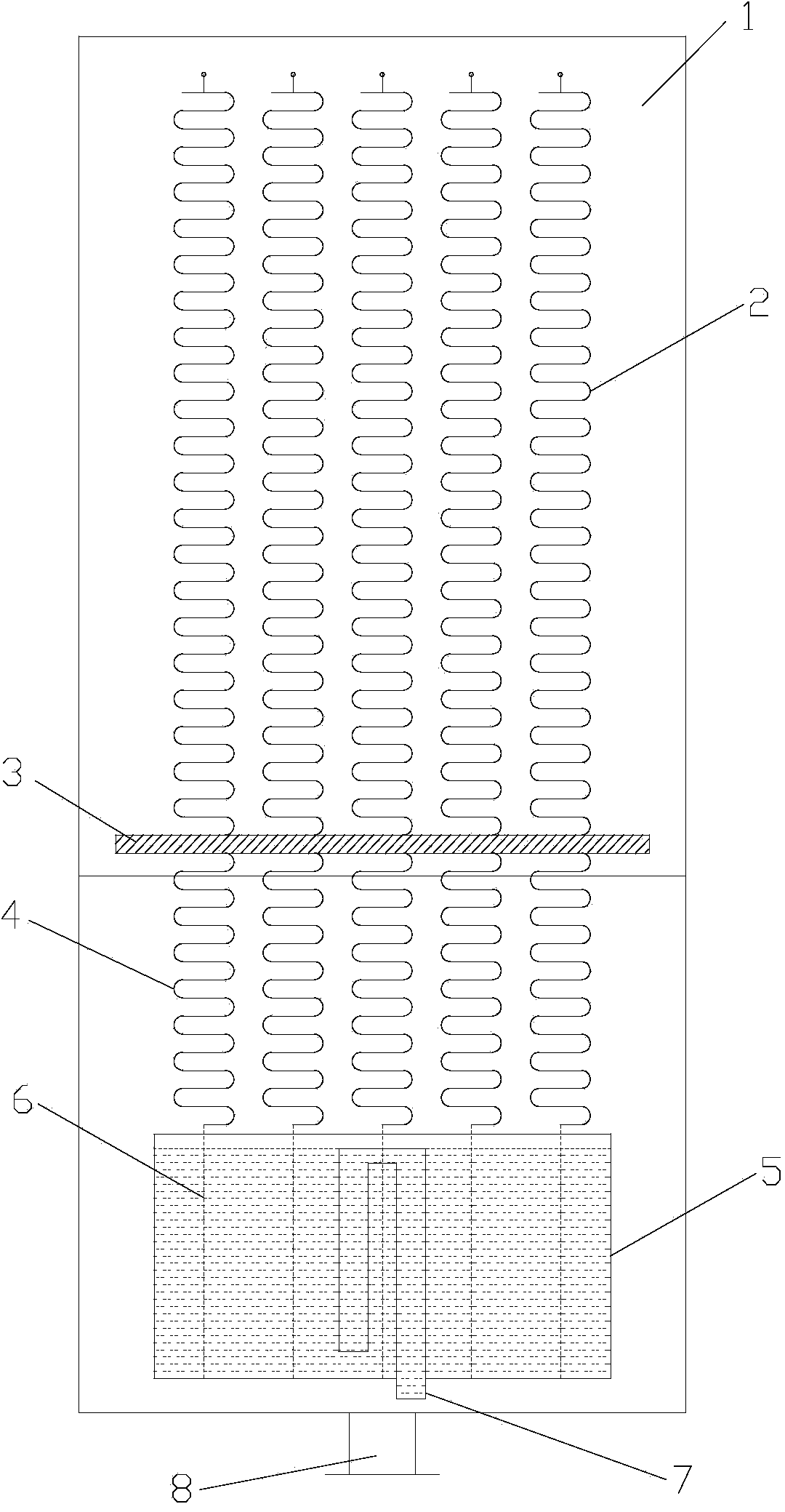
[0027] like Figure 1 to Figure 8 As shown, the automatic ash removal plate-type falling film generating device utilizing flue gas waste heat of the present invention includes a housing, n falling film units located in the housing, a suspended liquid contact box 5 , a suspension wire 6 and a siphon 7 . A solution outlet 8 is provided at the bottom of the housing. Each falling film unit includes a falling film plate 1 , an upper S-shaped planar spring 2 , a lower S-shaped planar spring 4 , a bar magnet 3 and a dust scraping device 9 . The falling film plate 1 in the n falling film units divides the inner cavity of the upper part of the casing into a flue gas heat source layer 10 and a solution layer 11 arranged at intervals. In each falling film unit, the upper S-shaped planar spring 2 , the lower S-shaped planar spring 4 and the bar magnet...


PUM


Abstract

The invention discloses an automatic dust removal board type falling film generation device utilizing waste heat of exhaust gas. The automatic dust removal board type falling film generation device comprises a shell, n falling film units, a suspended liquid receiving tank, a suspension line and a siphon. A solution outlet is formed in the bottom end of the shell. Each falling film unit comprises a falling film board, an upper section S-shaped planer spring, a lower section S-shaped planer spring, a bar magnet and a dust scraping device, wherein the bar magnet and the dust scraping device are located on the two sides of the falling film board, the top end of the upper section S-shaped planer spring is connected with the wall face of the falling film board, the bottom end of the upper section S-shaped planer spring is connected with the top face of the bar magnet, the top end of the lower section S-shaped planer spring is connected with the bottom face of the bar magnet, and the bottom end of the lower section S-shaped planer spring is connected with the suspended liquid receiving tank. The siphon is located inside the suspended liquid receiving tank. According to the automatic dust removal board type falling film generation device, the siphon principle is utilized, by the arrangement of the S-shaped planer springs for automatic and reciprocating washing, springs on the falling film walls can move in an automatic and reciprocating mode, channeling or plumes can be effectively restrained from being generated, the liquid film distribution is uniformed, and the falling film generation device has the automatic scale removal function.

Description

technical field [0001] The invention belongs to the technical field of absorption refrigeration utilizing waste heat of flue gas, and in particular relates to an automatic ash-removing plate type falling film generating device utilizing waste heat of flue gas. Background technique [0002] Most of the existing absorption refrigeration generators are immersion type and spray type. The immersion type generator is greatly affected by the static pressure of the liquid, which will increase the saturation temperature of the solution inside the liquid, weaken the driving force and reduce the out of range. The spray generator can effectively overcome the influence of hydrostatic pressure, but it is difficult to completely wet the heat transfer surface, and the heat transfer effect will also be affected. Using a falling film generator can effectively avoid the influence of the static pressure of the solution. However, due to the change of the physical properties of the falling film ...

Claims


Application Information

Patent Timeline
Patent Type & Authority Applications(China)
IPC IPC(8): F25B33/00
Inventor 杨柳杜垲
Owner 山东东岳能源交口肥美铝业有限责任公司
Learn More