Synchronous rectification driving circuit

A technology of synchronous rectification and drive circuit, which is applied in the direction of electrical components, adjustment of electric variables, high-efficiency power electronic conversion, etc., can solve problems such as false shutdown, eliminate false actions, and increase the source level of intelligent synchronous rectification controllers The effect of detecting terminal voltage and avoiding malfunction

Active Publication Date: 2014-08-20
西安唯电电气技术有限公司
View PDF4 Cites 8 Cited by
  • Summary
  • Abstract
  • Description
  • Claims
  • Application Information

AI Technical Summary

Problems solved by technology

After the switch is turned on, the source-to-drain voltage will drop to R DSon ·I D , and at this time there will be parasitic oscillation between the leakage inductance of the transfo

Method used


Image

  • Synchronous rectification driving circuit
  • Synchronous rectification driving circuit
  • Synchronous rectification driving circuit

Examples


Embodiment Construction

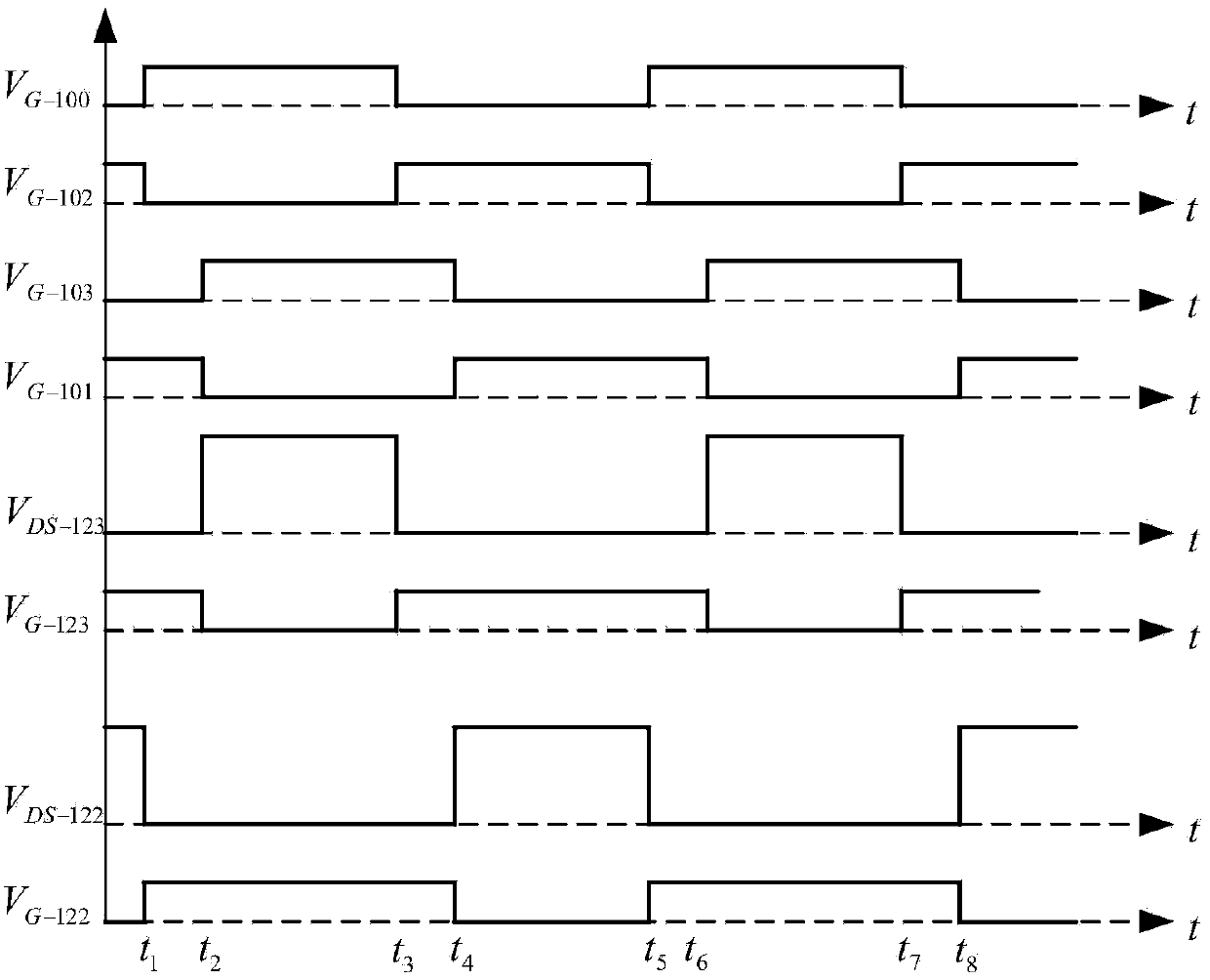
[0039] In the following specific embodiments, the present invention will be described in detail with the actual application waveform. In order to make the subject of the invention more prominent, the front end of the transformer (110) will not be described in detail below. principle.

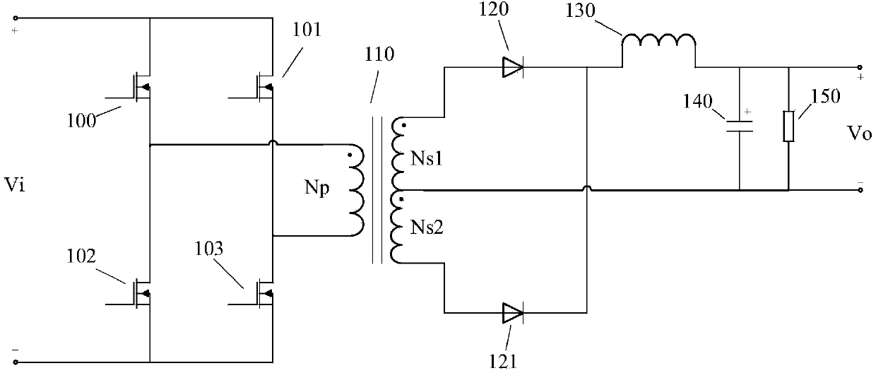
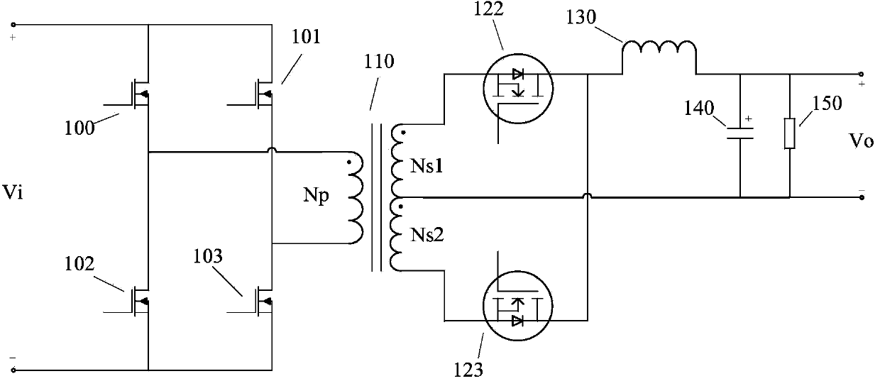
[0040] Figure 5 As shown, the present invention is a schematic diagram of a synchronous rectification drive circuit on the secondary side of a phase-shifted full-bridge converter.

[0041] The synchronous rectification drive circuit includes four full-bridge power MOS transistors connected in parallel to the power supply end, including MOS transistor a100, MOS transistor b101, MOS transistor c102, and MOS transistor d103, wherein the drain terminals of the MOS transistor a100 and the MOS transistor b101, The source terminals of MOS tube c102 and MOS tube d103 are connected to the power supply, the source terminal of MOS tube a100 and the drain terminal of MOS tube c102 are connected to the pri...


PUM


Abstract

The invention discloses a synchronous rectification driving circuit. The synchronous rectification driving circuit comprises four MOS tubes connected to a power source end in parallel. The MOS tube a and the MOS tube b are connected with a power source. The four MOS tubes are connected with the primary level of a transformer, the secondary level dotted terminal of the transformer is connected with a synchronous rectification tube a and is connected with an output filter inductor in series, a secondary center tap of the transformer is connected with a set of output filter capacitors and a load in parallel, or the secondary center tap of the transformer is connected with the output filter inductor in series, and then the secondary center tap of the transformer and the synchronous rectification tube a are connected with the output filter capacitors and the load in parallel. The secondary non-dotted terminal of the transformer and a node between the synchronous rectification tube a and the output filter inductor are connected with the synchronous rectification tube b. An active pole voltage conditioning circuit is connected between the secondary non-dotted terminal of the transformer and the synchronous rectification tube a in parallel. An intelligent synchronous rectification control chip IR1167 is connected between the synchronous rectification tube b and the active pole voltage conditioning circuit in parallel. The combined circuit improves the stability of synchronous rectification driving, and the synchronous rectification tube error movement caused by parasitic oscillation is avoided.

Description

technical field [0001] The invention relates to the field of switching power supplies, in particular to a synchronous rectification drive circuit in the switching power supply. Background technique [0002] In the occasion of inputting high voltage and outputting low voltage and high current, such as figure 1 In the full-wave rectification circuit shown, the current flows through the rectifier diode 120 (or 121 ) in one half cycle, and the current flows through the other rectifier diode 121 (or 120 ) in the other half cycle. Compared with the bridge rectifier circuit, the full-wave rectifier circuit saves half of the rectifier devices, and the rectifier circuit also reduces the primary tube voltage drop, so it is widely used in occasions where the output voltage is low. Due to the limited conduction capacity of a single diode, the output rectifier diode 120 and 121 are generally connected in parallel by multiple diodes. However, due to the high conduction voltage drop of t...

Claims


Application Information

Patent Timeline
IPC IPC(8): H02M3/335H02M1/08H02M7/219
CPCY02B70/1475Y02B70/10
Inventor 吕剑代杰仕
Owner 西安唯电电气技术有限公司
Why Eureka
Try Eureka