Continuous feed metering device

A technology of granular materials and rotors, applied in the direction of transportation and packaging, conveying bulk materials, conveyors, etc., can solve the problems of downstream applications, unstable reactor operation, unstable catalyst feeding, etc., to reduce wear, reduce The effect of rotation rate

Inactive Publication Date: 2016-11-02
TOTAL RES & TECH FELUY
View PDF9 Cites 0 Cited by
  • Summary
  • Abstract
  • Description
  • Claims
  • Application Information

AI Technical Summary

Problems solved by technology

This leads to mechanical wear of the equipment and erratic feed of catalyst, which eventually leads to erratic reactor operation
[0005] Furthermore, such systems deliver a fixed amount of granular material to the reactor discontinuously; in other words, there are regular variations in flow rate
This can have an impact on downstream applications
For example, it is well known in the industry that discontinuous feeding of catalyst to a polymerization reactor means that it is difficult to maintain constant reaction conditions and stable operation

Method used


Image

  • Continuous feed metering device
  • Continuous feed metering device
  • Continuous feed metering device

Examples


Embodiment

[0103] Calculation of cavity volume.

[0104] The cavity of the rotor can have a volume that depends on several factors including desired dispense rate, rotor speed, size and application. As a general guide, when the application is distributing catalyst for a polymerization reactor, the cavity of the rotor may have a diameter of about 1 to about 100 cm 3 , preferably about 20 to about 70 cm 3 , more preferably from about 20 to about 100 cm 3 volume.

[0105] The cavity of the rotor may have a volume calculated according to equation [1]. For a reactor with a production capacity Q (ton / h), a catalyst with a productivity P (gPE / g catalyst), and a catalyst bulk density MVA (g / cm 3 ), the rotational speed RPM of rotor, calculate volume V, it is the required volume in one rotation of the device of the present invention that comprises two rotors:

[0106] V = Q . 10 6 ...


PUM


Abstract

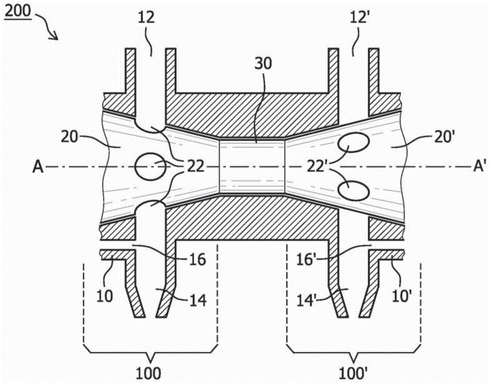
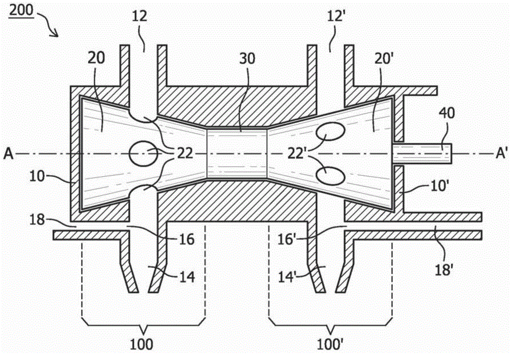
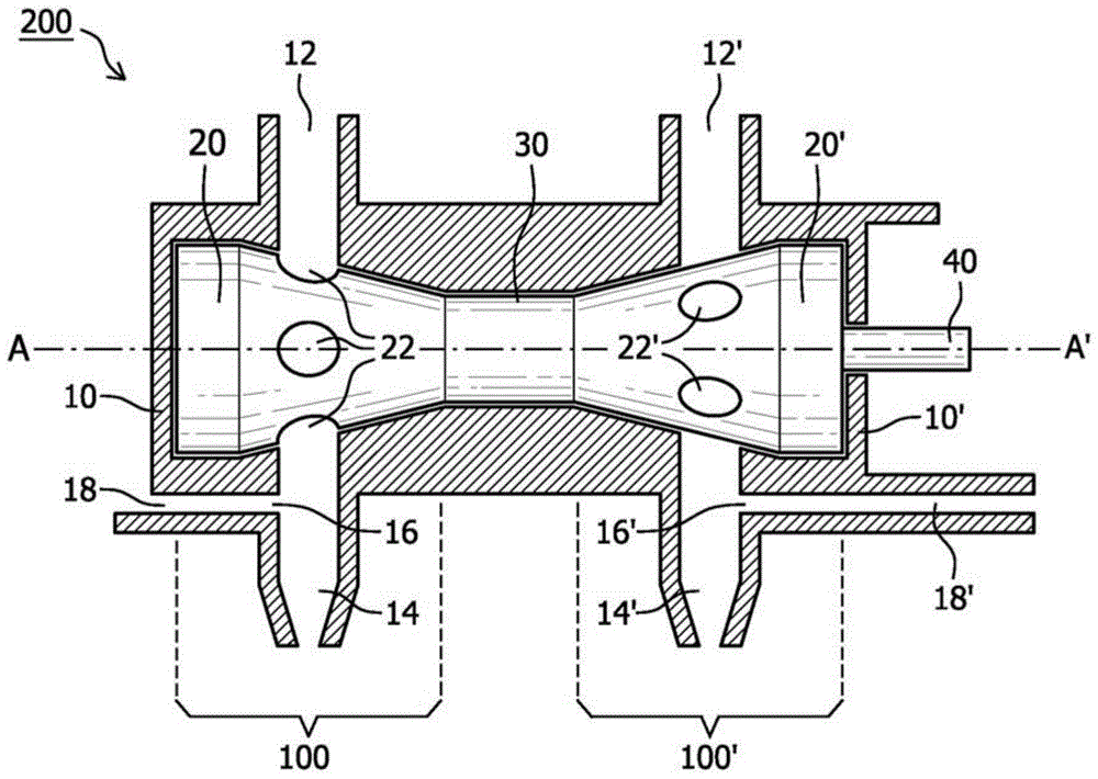
The present invention relates to a device (200) for dispensing a particulated material comprising: at least two rotary valves (100, 100'), each having a stator (10, 10') provided with an inlet (12, 12') and outlet (14, 14') for the particulated material, and a rotor (20, 20') seated in the stator (10, 10') sealing the inlet (12, 12') from the outlet (14, 14'), each rotor disposed with at least one chamber (22, 22') for receiving and dispensing the particulated material as the rotor (20, 20') turns around its central axis (A-A'); wherein the rotors (20, 20') are configured to rotate synchronously; wherein the chambers (22, 22') of at least two rotors (20, 20') are configured to dispense particulated material asynchronously, and wherein the rotors (20, 20') of the device (200) are configured such that the combined flow of particulated material is essentially continuous. The invention also relates to a method for dispensing a particulated material.

Description

technical field [0001] The present invention relates to a delivery system for continuously dispensing controlled quantities of dry or slurried particulate material. In particular the invention relates to catalyst delivery means for introducing catalyst into a polymerization reactor. Background technique [0002] Many manufacturing processes depend on distributing granular materials in a controlled manner for downstream applications. The process can be sensitive to the amount of granular material introduced, so it is important to control its flow and minimize any changes in flow rate. In particular, reactions such as polymerization are sensitive to the amount of catalyst introduced. Controlling the flow of catalyst to the reactor is important because unforeseen or uncontrolled catalyst injection in the reactor can result in reactions that exceed the cooling capacity of the reactor. [0003] Typically, a metering system is employed to dispense the granular material utilizin...

Claims


Application Information

Patent Timeline
Patent Type & Authority Patents(China)
IPC IPC(8): B01J8/00C08F2/34B65G53/46
CPCB01J8/002B01J8/003B01J8/0045B01J2208/00752B01J2208/00761B01J2208/00787
Inventor Y.布库奥尤伊A.弗南德兹
Owner TOTAL RES & TECH FELUY
Why Eureka
Try Eureka