Fiber structure intended to reinforce composite material parts and including a portion having a reduced thickness

A fiber structure and composite material technology, applied in the field of reinforced fiber structure, can solve problems such as fiber density change

Active Publication Date: 2014-08-20
SN DETUDE & DE CONSTR DE MOTEURS DAVIATION S N E C M A
View PDF9 Cites 11 Cited by
  • Summary
  • Abstract
  • Description
  • Claims
  • Application Information

AI Technical Summary

Problems solved by technology

[0005] Furthermore, because of the weaves that exist on the surface of the fabric, such as satin weaves, all floating yarns that exist after the last interlocking point of the yarns that have been taken out of the fibers need to be cut, thereby locally causing significant changes in fiber density

Method used


Image

  • Fiber structure intended to reinforce composite material parts and including a portion having a reduced thickness
  • Fiber structure intended to reinforce composite material parts and including a portion having a reduced thickness
  • Fiber structure intended to reinforce composite material parts and including a portion having a reduced thickness

Examples


Embodiment Construction

[0034] The invention is generally applied to the manufacture of fibrous structures suitable for the construction of fibrous reinforcements, called preforms, used in the manufacture of composite material components, in particular aeroengine blades, obtained by densifying the fibrous structure with a matrix. Typically, the matrix is ​​manufactured from resins for composites, using composites to relatively low temperatures, typically up to 300°C, or by refractory materials such as carbon or ceramics for thermal structural composites.

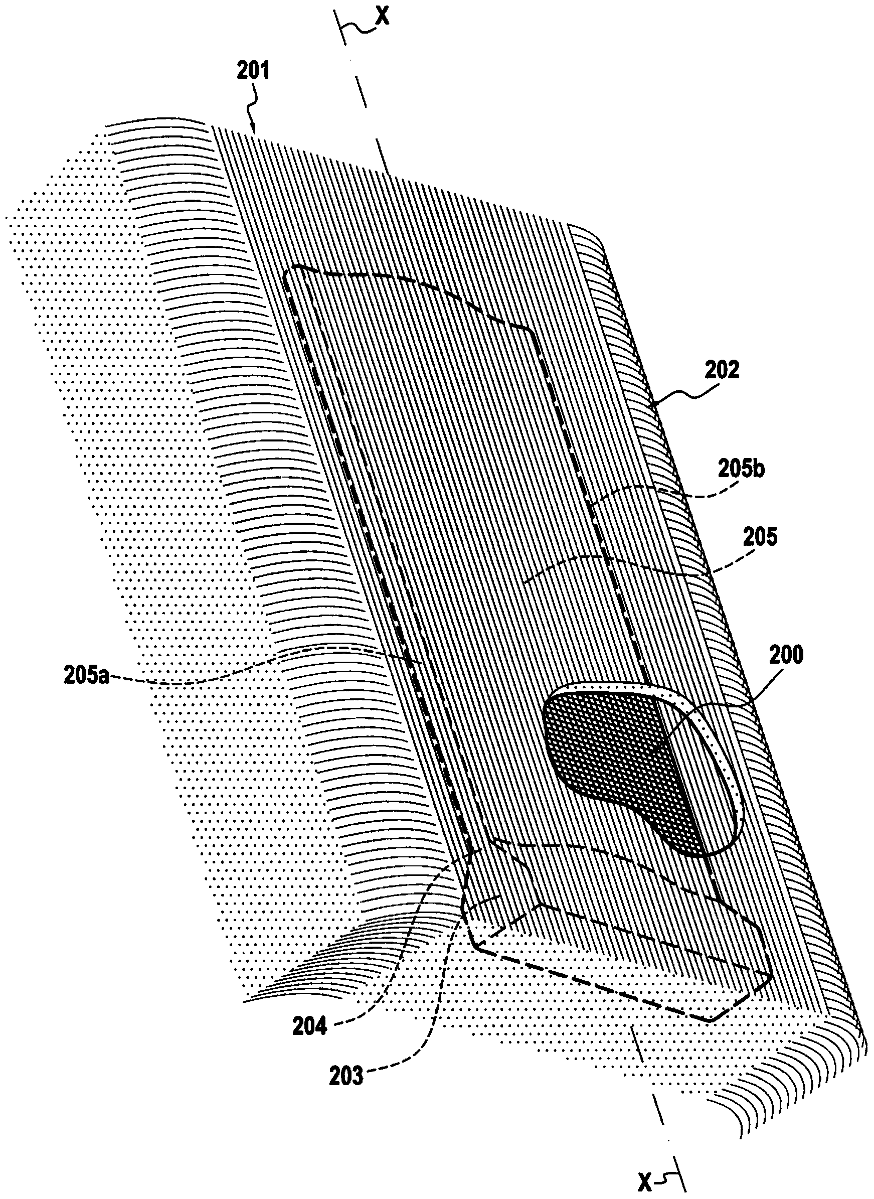
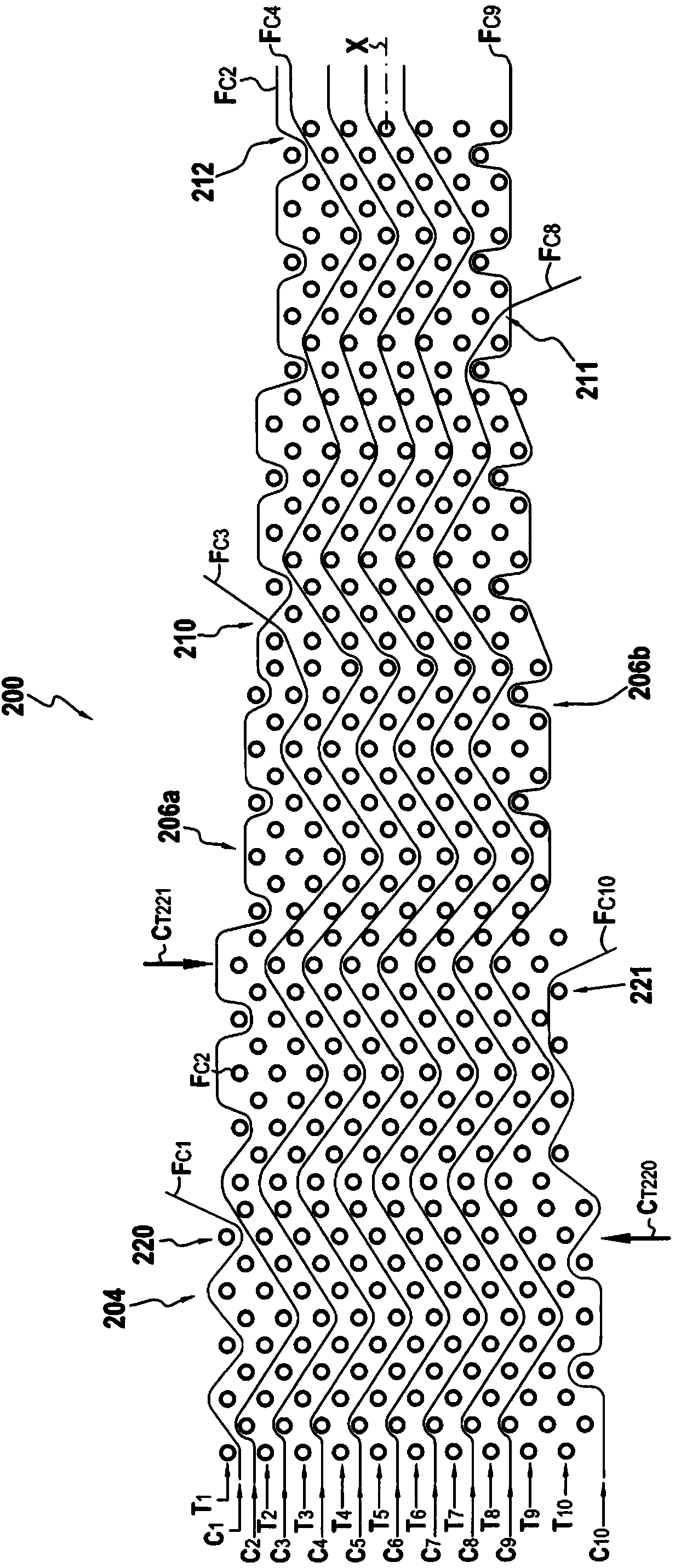
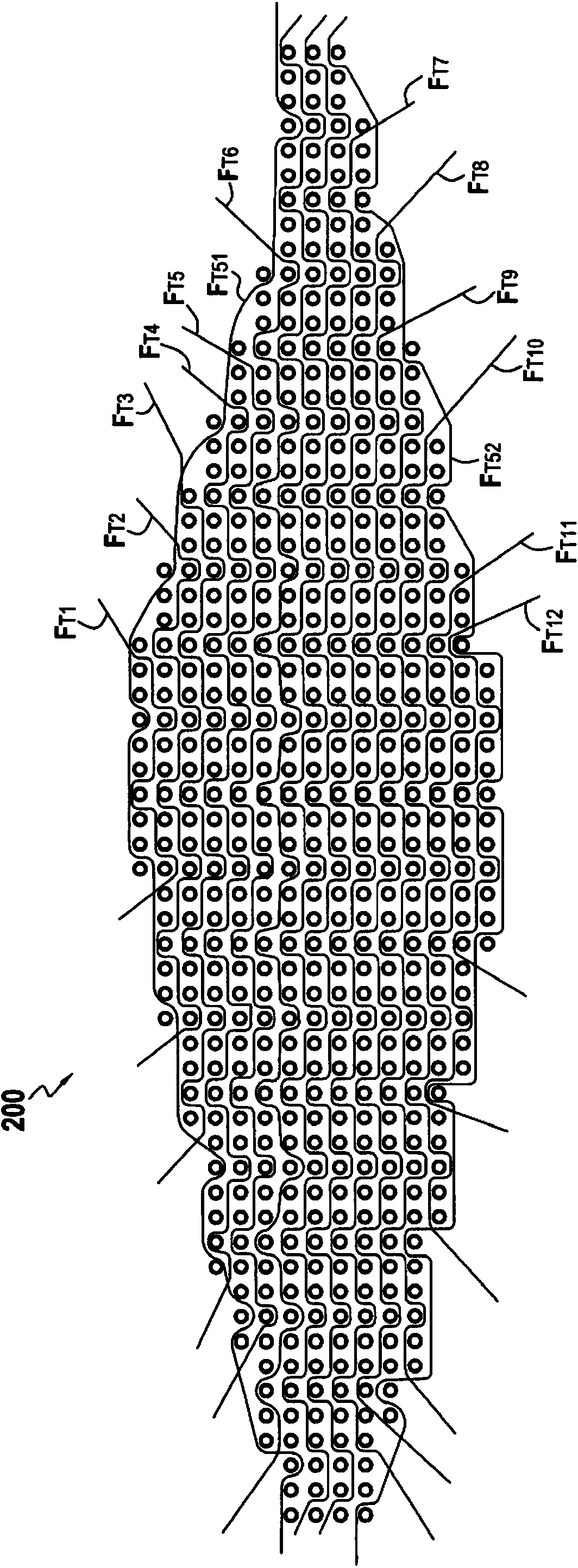
[0035] FIG. 1 is a detailed schematic illustration of a fiber-reinforced fiber structure 200 for forming an aeroengine blade.

[0036] The fibrous structure 200 is obtained by multilayer weaving, which is carried out in a known manner using a Jacquard type loom having a bundle or strand of warp yarns 201 organized in multiple layers, the warp yarns It is interlocked with the weft yarn 202 which is also arranged in multiple layers. Examples of the ...


PUM


Abstract

The invention relates to a fiber structure (200) for reinforcing a composite material part woven into a single part by means of multilayer weaving between a first plurality of thread layers (C1-C10) and a second plurality of thread layers (T1-T10). The fiber structure includes a portion (204) having a decreasing thickness and has a plurality of surface continuity thread setback portions (210, 211, 212) on said portion, wherein each portion has threads (Fc3; Fc8; Fc4), from a thread layer (C3; C8; C4) of the first thread layer plurality underlying the thread layer of the first thread layer plurality located on the surface of the structure, that are interrupted, and several surface discontinuity thread setback portions (220, 221), wherein each portion has threads (Fc1; Fc10), from the thread layer (C1; C10) of the first thread layer plurality located on the surface of the structure, that are interrupted. Each interrupted thread (Fc1; Fc10) is replaced, on the surface of the structure, by a thread (Fc2; Fc9) from a thread layer (C2; C9) underlying the first thread layer plurality. The threads from the layers from the second thread layer plurality (T1- T10), located on the surface of the fiber structure, are continuous over at least the entire portion (204) having a decreasing thickness.

Description

Background technique [0001] The present invention relates to the manufacture of components from composite materials, and more particularly to the manufacture of reinforcing fiber structures for such components. [0002] A particular field of application of the invention lies in the manufacture of structural composite components, ie components having a fiber-reinforced structure densified by a matrix. Composites make it possible to manufacture parts that weigh less in total than the same parts when manufactured from metal. [0003] In the context of fabricating fiber structures by multilayer weaving to create fiber reinforcements for composite parts, such as for aeroengine blades, yarns in the warp and weft directions must be withdrawn during weaving of the structure to match For example, reduction of part thickness in fixation or in the trailing edge of the blade to obtain a fiber preform with the blade's quasi-net shape (ie with its "clean shape") and dimensions. Withdrawin...

Claims


Application Information

Patent Timeline
Patent Type & Authority Applications(China)
IPC IPC(8): D03D25/00B29C70/24F01D5/28
CPCB29C70/24F05D2230/50F01D5/286F01D5/3092F01D5/147F01D5/288D03D25/005Y02T50/672Y02T50/60B29B11/16D03D25/00
Inventor 布鲁诺·杰克斯·杰拉德·达米布瑞恩多米尼克·酷派乔纳森·戈林吉恩-诺尔·马修
Owner SN DETUDE & DE CONSTR DE MOTEURS DAVIATION S N E C M A
Why Eureka
Try Eureka