Exhaust Heat Recovery Device

A technology of exhaust heat recovery and exhaust pipes, which is applied in the direction of exhaust devices, exhaust treatment, noise reduction devices, etc., can solve problems such as inability to perform heat exchange, reduce heat recovery losses, improve recovery efficiency, and suppress heat dissipation Effect

Active Publication Date: 2016-10-26
FUTABA IND CO LTD
View PDF7 Cites 0 Cited by
  • Summary
  • Abstract
  • Description
  • Claims
  • Application Information

AI Technical Summary

Problems solved by technology

For example, when most of the heat exchange medium flows into a part of the parallel short flow path, sufficient heat exchange cannot be performed.

Method used


Image

  • Exhaust Heat Recovery Device
  • Exhaust Heat Recovery Device
  • Exhaust Heat Recovery Device

Examples


Embodiment Construction

[0040] Hereinafter, this specific embodiment will be described in detail with reference to the accompanying drawings.

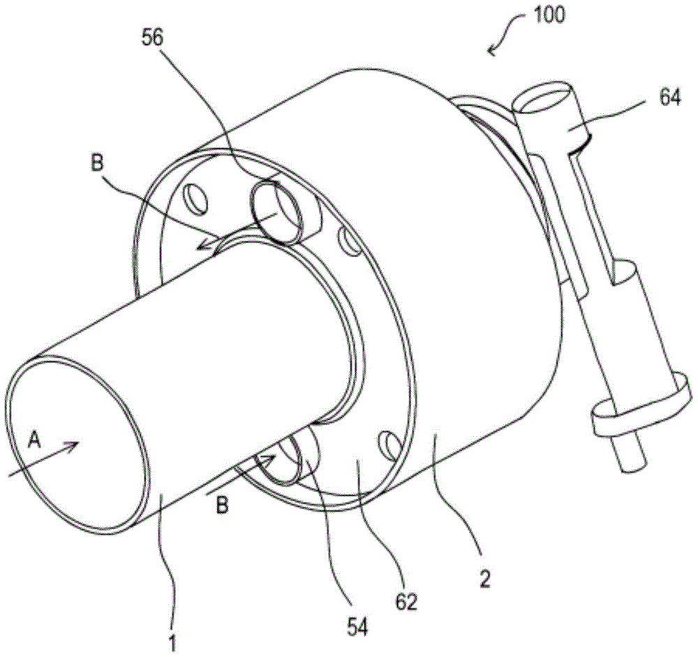
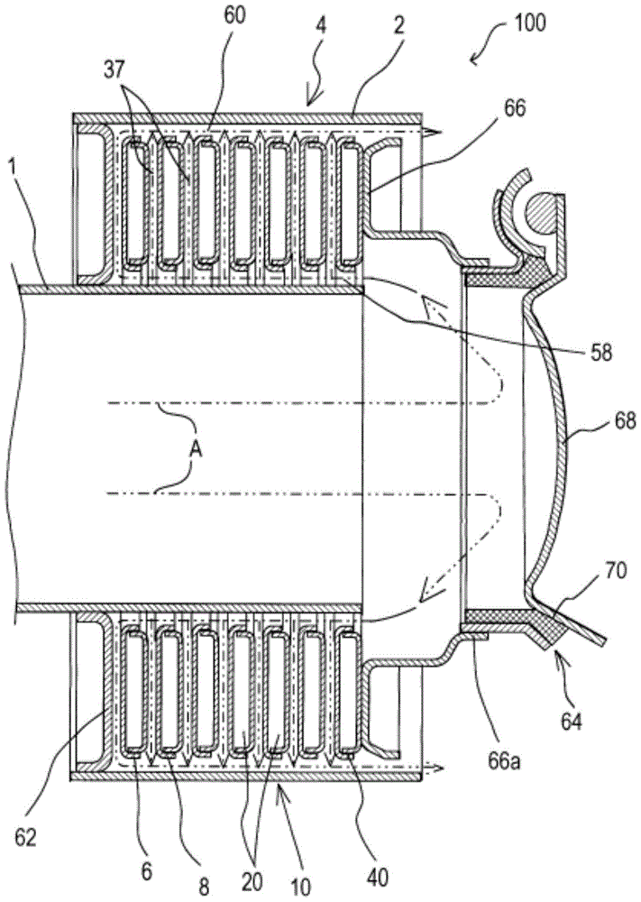
[0041] Such as figure 1 , figure 2 As shown, the exhaust heat recovery device 100 includes an exhaust pipe 1 , a cylindrical case 2 , and an exhaust heat recovery unit 4 as main components. The upstream side connection of the exhaust pipe 1 starts from the exhaust flow path of the internal combustion engine, and the exhaust pipe 1 is configured to guide the exhaust gas A from the internal combustion engine from the upstream side to the downstream side. A cylindrical case 2 covering the exhaust pipe 1 is provided outside the exhaust pipe 1 . The exhaust pipe 1 is disposed inside the cylindrical case 2 so as to be spaced apart from the exhaust pipe 1 , and a space is formed between the outer periphery of the exhaust pipe 1 and the inner periphery of the cylindrical case 2 . In this embodiment, the exhaust pipe 1 and the cylindrical casing 2 are arranged co...


PUM


Abstract

An exhaust gas heat recovery device of the present invention recovers heat of an exhaust gas from an internal combustion engine. The exhaust gas heat recovery device includes an exhaust pipe (1) that leads the exhaust gas from an upstream side to a downstream side, a cylindrical shell (2) that covers an outside of the exhaust pipe, and an exhaust gas heat recovery section (4) that is interposed between the exhaust pipe and the cylindrical shell and that performs heat exchange between the exhaust gas and a heat exchange medium. The exhaust gas heat recovery section includes a stacked body (10) that is composed by stacking a plurality of jacket parts (6, 8) each having a heat exchange medium conduit provided thereinside. In the stacked body, the respective heat exchange medium conduits (20) in the plurality of jacket parts are serially connected to each other.

Description

[0001] Cross References to Related Applications [0002] This international application claims priority from Japanese Patent Application for Invention No. 2011-281468 filed at the Japan Patent Office on December 22, 2011, the entire contents of which are incorporated herein by reference. technical field [0003] The present invention relates to an exhaust heat recovery device installed in an exhaust gas flow path from an internal combustion engine to recover exhaust heat by exchanging heat between exhaust gas and a heat exchange medium. Background technique [0004] As described in Patent Document 1, there is known a device that is installed in an exhaust flow path to exchange heat between exhaust gas from an internal combustion engine and a heat exchange medium such as cooling water of the internal combustion engine to recover exhaust heat. In this device, a tube stack is formed by stacking a plurality of circular donut-shaped flat tubes, an exhaust pipe is inserted into th...

Claims


Application Information

Patent Timeline
Patent Type & Authority Patents(China)
IPC IPC(8): F01N5/02
CPCF01N5/02F01N2240/02F28D9/0012F28D9/0043F28D21/0003F28F27/00Y02T10/12
Inventor 加藤久幸大上裕久
Owner FUTABA IND CO LTD
Why Eureka
Try Eureka