Three-dimensional oval vibration turning head

A technology of elliptical vibration and turning tool post, which is applied in the direction of large fixed members, metal processing machinery parts, metal processing equipment, etc., can solve the problems of reducing device versatility, processing time and materials, and frequency dependence, so as to simplify control and reduce Motion-coupled, versatile effects

Active Publication Date: 2014-08-27
DALIAN JIAOTONG UNIVERSITY
View PDF9 Cites 9 Cited by
  • Summary
  • Abstract
  • Description
  • Claims
  • Application Information

AI Technical Summary

Problems solved by technology

[0003] The current elliptical vibration cutting devices mainly include resonance type and non-resonance type. The main disadvantages of the resonance type elliptical vibration device are: (1) The frequency of elliptical motion depends on the nonlinear structural dynamic parameters of the cutter bar. In order to obtain reasonable parameters Need to optimize the tool holder size, reducing the versatility of the device
(2) The drive signal needs to be adjusted repeatedly to make the device resonate, and the tool holder needs to be specially designed, which has poor versatility
(4) The obtained ellipse distortion
[0004] The main disadvantages of the current non-resonant three-dimensional elliptical vibration device are: (1) The vibration of the device is realized by multiple kinematic pairs, which requires assembly and requires high precision for each part
(2) The cooperation of each part will produce friction loss and motion clearance
(3) Huge volume, time-consuming and material-consuming processing, difficult installation
(4) Poor versatility, cannot be applied to multiple types of lathes

Method used


Image

  • Three-dimensional oval vibration turning head
  • Three-dimensional oval vibration turning head
  • Three-dimensional oval vibration turning head

Examples


Embodiment Construction

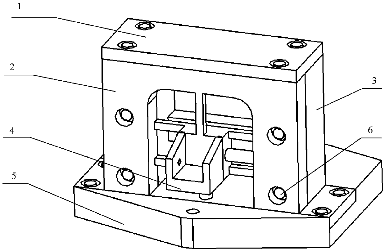
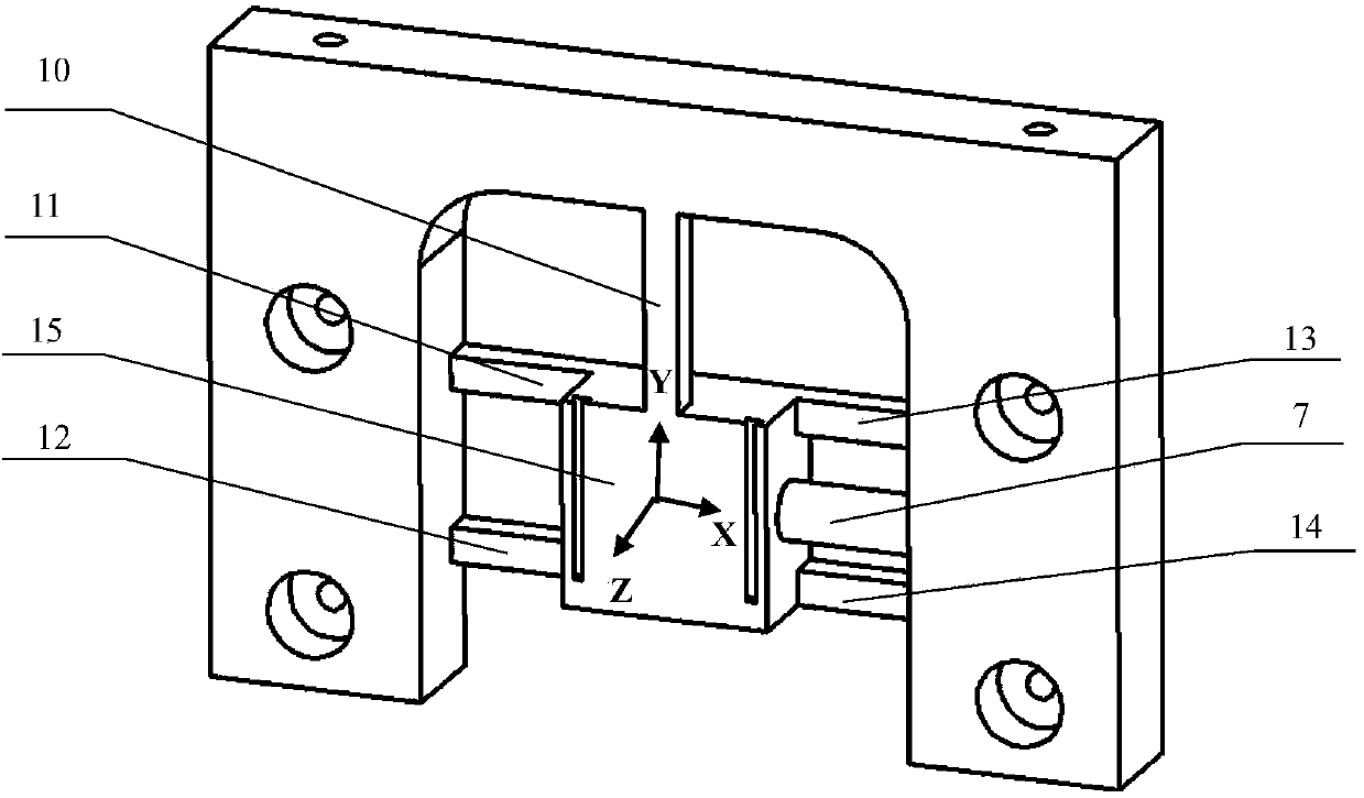
[0023] The present invention will be further described below in conjunction with the accompanying drawings. Such as figure 1 As shown, the micro-motion platform 15 is linked to the base 3 through the compliance unit A10, the compliance unit B11, the compliance unit C12, the compliance unit D13, and the compliance unit E14. The compliant unit B11, the compliant unit C12, the compliant unit D13, and the compliant unit E14 are arranged in parallel and distributed in the same plane with equal lengths. Compliant unit A10 is perpendicular to compliant unit B11 , compliant unit C12 , compliant unit D13 and compliant unit E14 , and is distributed in another plane. The two planes are parallel and have a certain distance. The micro-motion platform 15, five compliant units and the base 3 form the vibrating part 2 as a whole, and the vibrating part 2 belongs to a three-degree-of-freedom compliant mechanism;

[0024] The fixture 4 is fixed to the micro-motion platform 15 through a T-sha...


PUM


Abstract

The invention discloses a three-dimensional oval vibration turning head which comprises a vibration component, a base, a top cover, three piezoelectric ceramics drivers, a fixture and a connecting plate. A micro-positioning platform is arranged in the center of vibration component, the vibration component is connected to a base body through fiver suppling units, the micro-positioning platform has three degrees of freedom which are X rotation, Y rotation and Z moving respectively, and the vibration component is a three-degree-of-freedom suppling mechanism and is an integral component. When the three-dimensional oval vibration turning head works, a turning tool of any type is connected to the micro-positioning platform through the fixture, the micro-positioning platform drives the turning tool to vibrate under the driving of the three piezoelectric ceramics drivers, and moving tracks at the position of a tool point are combined into a three-dimensional oval. Due to the fact that the vibration component is the three-degree-of-freedom suppling mechanism, the vibration component of the turning head does not need to be assembled and positioned, and friction losses and moving gaps are avoided. Due to the fact that the piezoelectric ceramics drivers are used for directly driving the micro-positioning platform, the phase angle, the amplitude and the frequency of the oval motion are made to be more convenient to adjust.

Description

technical field [0001] The invention belongs to the field of difficult-to-machine material cutting and ultra-precision cutting, in particular to a three-dimensional elliptical vibration turning tool holder. Background technique [0002] In traditional cutting methods, the cutting process of turning difficult-to-machine materials often leads to severe tool wear, deterioration of machined surface quality, and reduced machining accuracy. In order to solve these problems and make precision machining more widely used in military, aerospace and civilian industries, researchers have proposed a series of solutions, such as: cryogenic cutting, carbon saturation cutting and vibration cutting. Among them, vibration cutting is the most promising cutting method, which has many advantages such as reducing cutting heat and cutting force, inhibiting tool wear, and improving the quality of machined surfaces. Experiments have confirmed that the workpiece processed by elliptical vibration cut...

Claims


Application Information

Patent Timeline
Patent Type & Authority Applications(China)
IPC IPC(8): B23B21/00
CPCB23Q1/25
Inventor 林盛杨亮孔晰王春徐剑
Owner DALIAN JIAOTONG UNIVERSITY
Why Eureka
Try Eureka