Buffering device of undercarriage buffering support

A buffer strut and buffer device technology, applied in the field of aircraft, can solve the problems of high requirements on structure and materials, difficult to adjust in a large range, limited adjustment range, etc., and achieve the effects of easy implementation, simple structure and large adjustment range.

Inactive Publication Date: 2015-03-25
COMAC +1
View PDF5 Cites 5 Cited by
  • Summary
  • Abstract
  • Description
  • Claims
  • Application Information

AI Technical Summary

Problems solved by technology

[0004] In order to improve the cushioning performance of the oil-air cushioning strut, designers in the field have made a lot of design attempts in terms of structural form and internal structure in recent years, such as technologies such as changing oil holes and double chambers, but the room for improvement is getting smaller and smaller
In addition, although the damping force of the existing oil-pneumatic buffer strut can change with the change of stroke and acceleration, its adjustment range is limited, and it is basically adjusted by the pre-ramping pressure of the air cavity. Range adjustment, so it is mostly passive control. In this case, the shock absorption effect will be significantly limited, and the initial stiffness of the aircraft landing is small, the cushioning efficiency is low, and the peak load during the cushioning process is obvious. The requirements for structure and materials higher

Method used


Image

  • Buffering device of undercarriage buffering support
  • Buffering device of undercarriage buffering support

Examples


Embodiment Construction

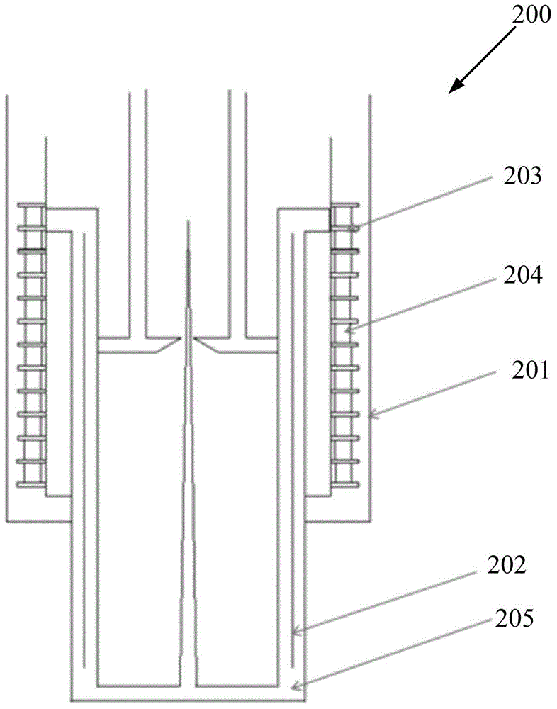
[0027] An embodiment of the buffer device of the landing gear buffer strut according to the present invention is as follows: figure 2 As shown, its typical composition includes three parts: the exciting part arranged on the inner side of the outer cylinder wall of the buffer pillar, the induction part on the inner cylinder of the buffer pillar, and the winding current control unit.

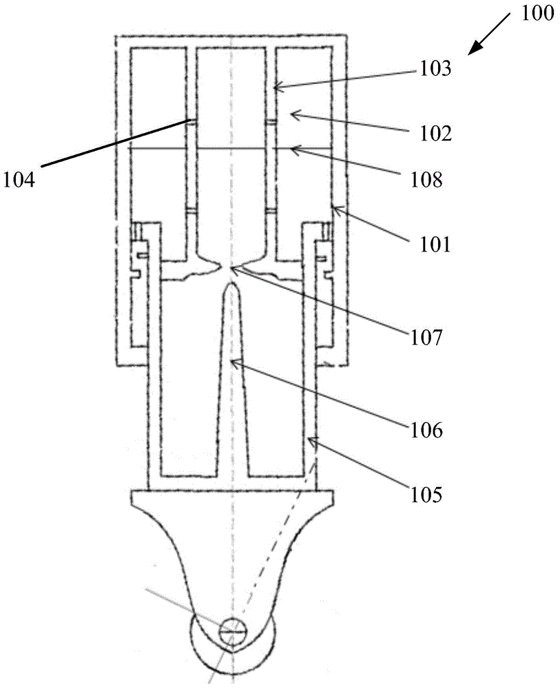
[0028] The buffer device according to the present invention can be applied to various existing buffer strut structures, especially oil-pneumatic buffer struts. compared to figure 1 The existing buffer strut 100 shown, in the improved buffer strut 200 of the present invention, the inner side of the outer cylinder wall 201 of the buffer strut is equipped with an exciting component, and a sensing component is installed at the lower end of the buffer strut, such as a displacement sensor ( not shown). The excitation components are mainly composed of silicon steel sheets 203 and three-phase windings ...


PUM


Abstract

The invention provides a buffering device of an undercarriage buffering support, and an application method of the buffering device to an oil-gas buffering support. The buffering support comprises an outer barrel and an inner barrel capable of moving along the inner wall of the outer barrel; the buffering device comprises at least one excitation part, at least one induction part, a control unit and a sensing part, wherein the at least one excitation part is distributed on the inner side of an outer barrel wall of the buffering support; the at least one induction part is distributed in the inner barrel of the buffering support and is used for responding excitation of the corresponding excitation, so that the inner barrel moves along the outer barrel of the buffering support to generate buffering damping; the control unit is used for controlling the excitation part in real time according to a movement signal of the buffering support; and the sensing part is distributed at the lower end of the buffering support and is used for detecting the movement signal of the buffering support and feeding the movement signal back to the control unit. According to the buffering device of the undercarriage buffering support, a relatively complicated outer condition is adapted according to a semi-automatic control manner and the airplane landing buffering efficiency is improved; and the safety and the comfort of an airplane landing process can be further increased by using a good control algorithm.

Description

technical field [0001] The present invention generally relates to the technical field of aircraft, in particular to a buffer device for a landing gear buffer strut. Background technique [0002] During the landing process of modern aircraft, the landing gear needs to bear a large impact load. In order to ensure the stability and safety of the landing process, the landing gear struts mostly adopt the structural form of installing oil-pneumatic buffer struts. [0003] figure 1 A typical oil and gas buffer strut is shown. In the structure of the oil-pneumatic buffer strut 100, the outer cylinder 101 of the buffer strut is connected to the upper mass, and the chamber containing the high-pressure gas, such as the nitrogen chamber 102, is located at the upper part of the strut inner cavity, and there is no separating piston between the oil and gas. An oil hole support pipe 103 is provided in the nitrogen chamber 102, and a small hole 104 is provided on it to keep the oil liquid ...

Claims


Application Information

Patent Timeline
Patent Type & Authority Applications(China)
IPC IPC(8): B64C25/58B64C25/60
CPCB64C25/60F16F9/50
Inventor 陈宝琦李生杰曹丹青王鸿鑫是贤珠
Owner COMAC
Why Eureka
Try Eureka