
Auto swirl exhaust

A technology for exhaust devices and automobiles, which is applied to exhaust devices, mufflers, engine components, etc., can solve problems such as ineffectiveness, and achieve the effects of low cost, reasonable and simple structure design, and reduced exhaust pressure.

Active Publication Date: 2017-01-11
GUANGXI UNIV
View PDF6 Cites 0 Cited by
  • Summary
  • Abstract
  • Description
  • Claims
  • Application Information

AI Technical Summary

Problems solved by technology

The secondary air injection system is a practical technology for exhaust emission control. Since the implementation of the world's first vehicle exhaust pollution control standard, it has been widely used in automobiles. Among them, the pulse type secondary air injection system has the function of applying its own emission Gas pressure pulse can achieve the purpose of reducing emissions without consuming engine power, but it can only be applied at idle speed or low speed operation, and it will not work at high speed operation

Method used


Image

  • Auto swirl exhaust
  • Auto swirl exhaust

Examples


Embodiment Construction

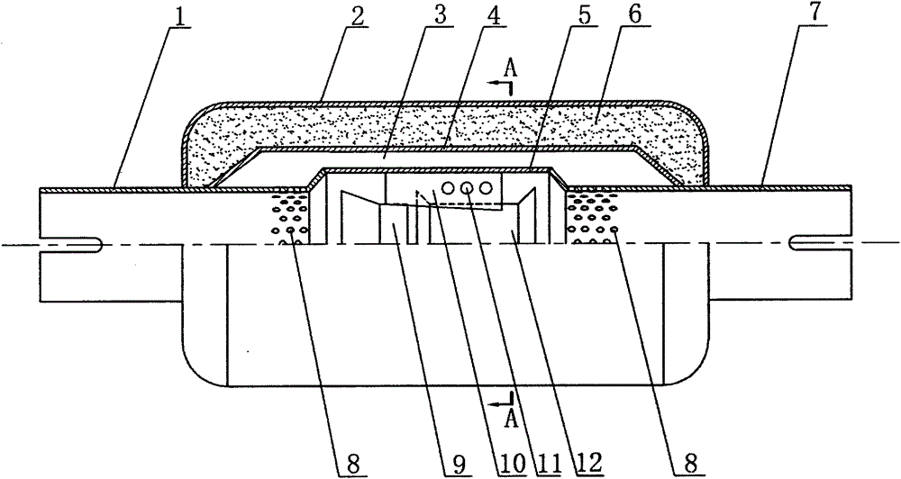
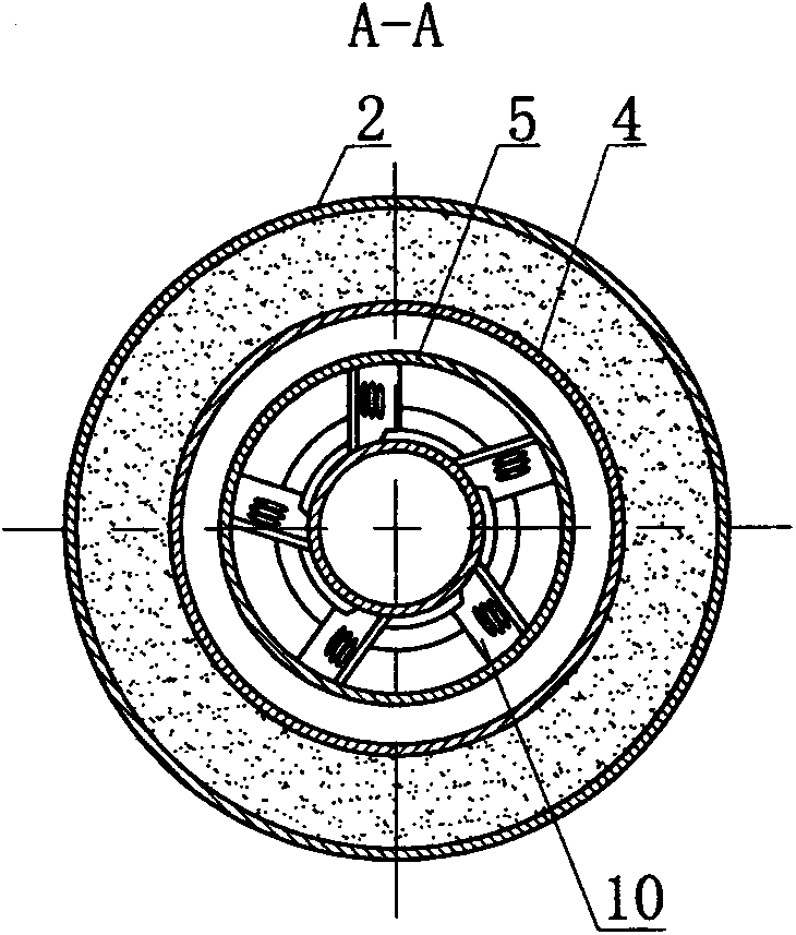
[0010] As shown in the drawings, the automobile swirl exhaust device of the present invention is composed of a housing part, a swirl decompression part, an intake pipe 1 and an exhaust pipe 7. The shell part includes an outer shell 2, a middle shell 4 and an inner shell 5. The outer shell 2 and the middle shell 4 enclose an asbestos-enriched area 6, and the asbestos-enriched area 6 is filled with asbestos. The middle shell 4, the inner shell 5, the intake pipe 1, and the exhaust pipe 7 encloses a recirculation zone 3, and the end connecting the intake pipe 1 and the exhaust pipe 7 to the inner shell 5 is bell-shaped, and there is a recirculation hole cluster 8 near the end of the bell-shaped end; the intake pipe 1 and the exhaust pipe 7 They are respectively fixedly connected with the inner shell 5, the middle shell 4 and the outer shell 2; the swirl decompression part is located in the inner shell 5, including the guide vane 10, the first horn tube 9 and the second horn tube 1...


PUM


Abstract

A rotational flow exhaust device of an automobile mainly comprises a shell body part, a rotational flow decompression part, an air inlet pipe and an exhaust pipe. The shell body part comprises an outer shell, a middle shell and an inner shell. An asbestos filling zone is defined by the outer shell and the middle shell, and a recirculation zone is defined by the middle shell and the inner shell. The air inlet pipe and the exhaust pipe are fixedly connected with the inner shell, the middle shell and the outer shell respectively. The rotational flow decompression part is located in the inner shell and comprises guide vanes, a first horn pipe and a second horn pipe. The first horn pipe and the second horn pipe are fixedly connected with the guide vanes respectively, the guide vanes are fixedly connected with the inner shell, and each guide vane is provided with three decompression holes. Tail gas of an engine enters the air inlet pipe, the pressure of the tail gas exhausted by the exhaust pipe reduces through the decompression effect of the rotational flow decompression part, the suction force of the negative pressure rises, the exhaust speed is increased, air inflow is increased, and fuel consumption is effectively reduced. The rotational flow exhaust device of the automobile is simple and reasonable in structure, low in cost, economical and practical.

Description

technical field [0001] The invention belongs to the technical field of automobiles, and relates to an automobile swirl exhaust device. Background technique [0002] Nowadays, with the development of cities, the number of motor vehicles is increasing, and the technical requirements for automobiles are also increasing. It is very important for automobiles to save fuel, so it is of great significance to improve the fuel utilization rate of automobile engines. The secondary air injection system is a practical technology for exhaust emission control. Since the implementation of the world's first vehicle exhaust pollution control standard, it has been widely used in automobiles. Among them, the pulse type secondary air injection system has the ability to apply its own exhaust Air pressure pulse can achieve the purpose of reducing emissions without consuming engine power, but it can only be applied at idling or low speed, and it will not work at high speed. Contents of the invent...

Claims


Application Information

Patent Timeline
Patent Type & Authority Patents(China)
IPC IPC(8): F01N13/00
Inventor 周清陈艳梅黄才贵滕庆庆韦志康张更娥
Owner GUANGXI UNIV
Learn More