High-power radial plunger pump

A radial column, high-power technology, applied in the mechanical field, can solve the problems of increasing radial size, large radial size space, large friction loss, etc., and achieves reduction of radial size, radial size reduction, and equipment weight. reduced effect

Active Publication Date: 2014-08-27
白巨章
View PDF6 Cites 13 Cited by
  • Summary
  • Abstract
  • Description
  • Claims
  • Application Information

AI Technical Summary

Problems solved by technology

[0004] This structure has the following disadvantages: 1. When the cam rotates, the plunger is always affected by the lateral force, the service life is short, and it cannot adapt to the high-pressure working environment
[0005] 2. There are many power transmission parts, the structure is complex, the radial dimension is increased, and the friction loss is large
[0006] 3. The spring occupies a large space in the radial dimension, which increases the volume of the entire pump body, wastes materials and increases the cost
[0007] 4. Each plunger can only inhale and discharge the liquid independently. There are too many external connection pipelines of the pump body. The theory of multi-cylinder work is feasible, but it is difficult to realize in practical application.

Method used


Image

  • High-power radial plunger pump
  • High-power radial plunger pump

Examples


Embodiment Construction

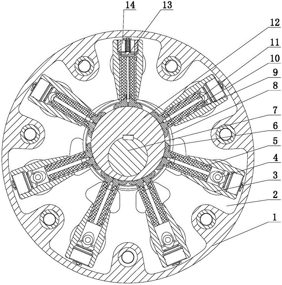
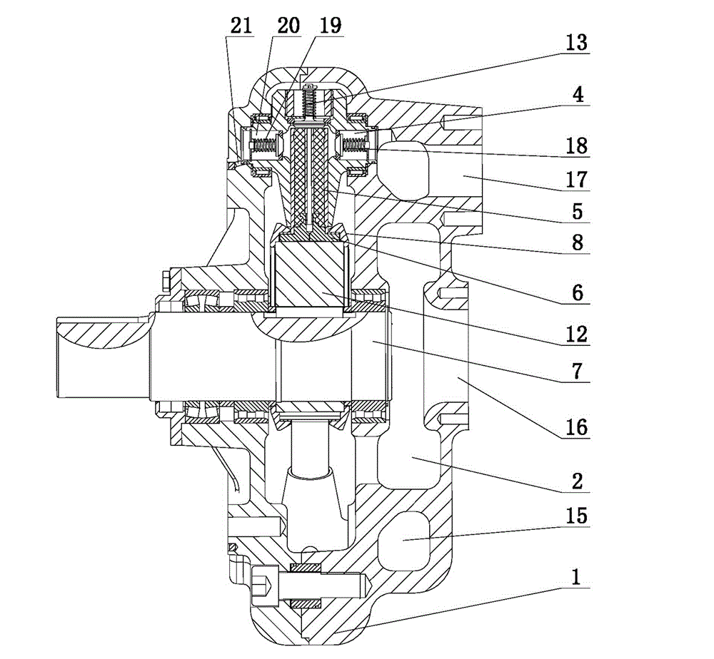
[0019] The present invention includes a housing 1 with a cavity 2 inside. The surface of the housing 1 is provided with a liquid suction port 16 communicating with the cavity 2, and the middle of the housing 1 is provided with a cam 12 through a rotating shaft 7, and the cam 12 is provided with a pull ring 8. At least two plungers 5; the end of each plunger 5 is arranged in a plunger cylinder 3, the end of the plunger cylinder 3 is provided with a liquid inlet 14 communicating with the cavity 2, and the liquid inlet 14 is provided There is a suction valve 13; both sides of the plunger cylinder 3 are provided with a first hollow trunnion 4 and a second hollow trunnion 20 that cooperate with the housing 1; an annular high-pressure chamber 15 is provided in the housing 1; The first hollow trunnion 4 of each plunger cylinder 3 is in communication with the annular high-pressure chamber 15. The first hollow trunnion 4 is provided with a drain valve 18 corresponding to the annular high...


PUM


Abstract

The invention provides a high-power radial plunger pump, belongs to the field of machinery and particularly relates to a high-power radial plunger pump. The high-power radial plunger pump is small in size, simple in structure, convenient to machine, long in service life and low in cost. The high-power radial plunger pump comprises a casing provided with a cavity in the inside, wherein the surface of the casing is provided with a liquid suction port communicated with the cavity. The high-power radial plunger pump is structurally characterized in that the middle of the casing is provided with a cam through a rotation shaft, and the cam is provided with at least two plungers through pull rings. The end of each plunger is arranged in a plunger cylinder, a liquid inlet communicated with the cavity is arranged at the end of the plunger cylinder, and a liquid suction valve is arranged in the liquid inlet. Two sides of the plunger cylinder are provided with first hollow lug shaft and a second hollow lug shaft which are matched with the casing. An annular high-pressure cavity is arranged in the casing. The first hollow lug shaft of each plunger cylinder is communicated with the annular high-pressure cavity, and a liquid discharging valve is arranged in the first hollow lug shaft corresponding to the annular high-pressure cavity. The surface of the casing is provided with a liquid outlet communicated with the annular high-pressure cavity.

Description

Technical field [0001] The invention belongs to the field of machinery. Specifically, the invention relates to a high-power radial plunger pump. Background technique [0002] Existing high-pressure and large-flow diaphragm pumps produced at home and abroad are all three-turn crankshaft plunger cylinders arranged horizontally, or double-turn crankshaft plunger cylinders are arranged horizontally. Because the plunger cylinders are arranged horizontally, the crankshaft support point span is too large. To ensure effective power output, the size of the crankshaft journal and other related parts must be increased. Therefore, the equipment with this structure is too large and heavy. [0003] The Chinese patent application number is 200910102304.8, and the name is the invention patent application of "Eccentrically Propelled Circular Distributed Plunger Pump". The published technical solution is to install a cam at the end of the driving shaft and set a bearing outside the cam. The bearing...

Claims


Application Information

Patent Timeline
Patent Type & Authority Applications(China)
IPC IPC(8): F04B1/053F04B53/16F04B53/14
Inventor 白巨章白庶王振动
Owner 白巨章
Why Eureka
Try Eureka