Multi-radar remote monitoring system and method based on WebSocket

A remote monitoring system and multi-radar technology, applied in transmission systems, radio wave measurement systems, electrical components, etc., can solve the problems of high update frequency, poor cross-platform performance, and small amount of operating status information, and improve reliability, Improve real-time performance and avoid delay effects

Active Publication Date: 2014-08-27
BEIHANG UNIV +1
3 Cites 34 Cited by

AI-Extracted Technical Summary

Problems solved by technology

However, the premise of this kind of solution is that the browser supports the corresponding plug-in and the client page JavaScript and Flash or Applet program can call each other across domains. At the same time, its dedicated port number is not restricted by the firewall, which limits its versatility and reliability. Scalability
[0007] In the multi-radar remote monitoring system, the update frequency of radar operating status is high (about 3HZ), the update time is unpredictable, and the amount of reported operating status information is small (less than 30 bytes). Combining the above several real-time Web application solutions, The polling based on HTTP protocol, Ajax long polling and Iframe streaming schemes are not suitable for building real-time web applications with high update frequency and small amount of data in a single update, and cannot meet the needs of web client radar in multi-radar remote monitoring systems. Real-time update requirements for operating status information
The solution based on browser plug-in (Flash XMLSocket, Applet) uses socket connection to real...

Abstract

The invention discloses a multi-radar remote monitoring system and method based on the WebSocket. Operating state information of radars is uniformly packaged in a CAT002 format and sent to a center server side, and after receiving the operating state information, in the CAT002 format, of the radars, the center server side analyzes and converts the operating state information into radar operating state messages in a JSON format, and then pushes the radar operating state messages to a Web client side in real time through Websocket connection; after receiving the radar operating state messages in the JSON format through Websocket connection, the Web client side displays operating states of radar stations in real time with electronic map data combined. Real-time performance of obtaining the operating state information of the radars through the Web client side is effectively promoted, and the operating states of the multiple radar stations can be monitored in real time in an unified mode.

Application Domain

Wave based measurement systemsTransmission

Technology Topic

Client-sideElectronic map +6

Image

  • Multi-radar remote monitoring system and method based on WebSocket
  • Multi-radar remote monitoring system and method based on WebSocket
  • Multi-radar remote monitoring system and method based on WebSocket

Examples

  • Experimental program(1)

Example Embodiment

[0039] The following will clearly and completely describe and discuss the technical solutions in the embodiments of the present invention with reference to the accompanying drawings of the present invention. Obviously, what is described here is only a part of the examples of the present invention, not all of the examples. All other embodiments obtained by those of ordinary skill in the art without creative work, all belong to the protection scope of the present invention.
[0040] In order to facilitate the understanding of the embodiments of the present invention, the following will take specific embodiments as examples for further explanation and description in conjunction with the accompanying drawings, and each embodiment does not constitute a limitation to the embodiments of the present invention.
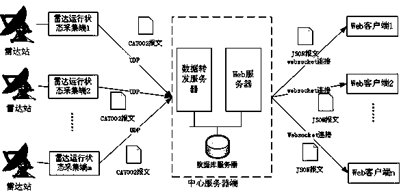
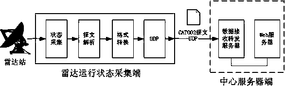
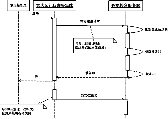
[0041] like figure 1 As shown, the Websocket-based multi-radar remote monitoring system disclosed in the present invention is composed of a radar operation status collection terminal, a central server terminal and a Web client; the radar operation status collection terminal is deployed at the radar site and is responsible for collecting the operation of the radar site. The status information is encapsulated in the format of EUROCONTORL ASTERIX Categoery002 (hereinafter referred to as CAT002), and sent to the control center server through UDP protocol; the center server is responsible for receiving the received data sent by the radar operating status collection end. The CAT002 format radar operating status information is parsed and converted into JSON format messages, and pushed to the Web client in real time through the Websocket connection, and the relevant information is stored in the database; the Web client is responsible for establishing and receiving the Websocket connection with the central server. The radar operating status message in JSON format forwarded by the central server is combined with the electronic map data to display the operating status of the radar site in real time on the Web page.
[0042] like figure 2 As shown in the figure, the radar operating state acquisition terminal is composed of an operating state acquisition module, a message parsing, a format conversion module, and a UDP module, wherein the operating state acquisition module is responsible for receiving the operating state message reported by the radar device through the COM port or the network interface. , the message parsing module extracts the required information after parsing, encapsulates it into a CAT002 format message by the format conversion module, and finally sends it to the central server through the UDP module. The radar operating state information extracted after being parsed by the message parsing module is uniformly output as a structured Radar_Info format, which is defined in one embodiment as:
[0043]
[0044] The radar_type, time, admin, and personnel fields are used to store the radar equipment type, message reporting time, management organization name, and personnel information. The lon and lat fields are used to store the latitude and longitude information of the radar site, and the state field is used to store the radar equipment. Running state information, the online, silent, offline and error states are coded as 0, 1, 2, 3 respectively; the azi, height and range fields are used to store the normal direction, erection height and detection range information respectively. The structures in the above embodiments can be expanded and modified according to specific needs to meet specific needs.
[0045] The format conversion module uniformly encapsulates the received operating status information into CAT002 format. The CAT002 format is defined in the radar service message transmission standard (standard number SUR.ET1.ST05.2000-STD-02b-01) of the Radar Data Exchange published by EUROCONTORL for radar sites and users. The message format for the exchange of radar-related service information between radar data processing centers. The CAT002 message format defined in the standard is shown in the following table:
[0046]
[0047] In an embodiment of the present invention, the CAT002 format is defined as the following structure:
[0048]
[0049]
[0050] Among them, the DataCAT field and the DataLen field are used to store the data packet type (fixed as 002) and the data packet length, and the FSPEC field is the data field specification field, which is used to identify which data items appear in the message and which are omitted; the fields data_source_SIC and data_source_SAC are respectively Used to store device type and area type, corresponding to I002/010 data item in CAT002 format definition; msg_type, sector_number, utc, antenna_rotation_period, station_rotaion_period, range, height, warning respectively correspond to I002/000, I002/020 in CAT002 format definition , I002/030, I002/041, I002\070 and I002\090, I002\080 data items. For the specific meaning and coding rules of each data item, please refer to the European management radar service message transmission standard document (standard number SUR.ET1.ST05. 2000-STD-02b-01). The station_config_state can be customized according to user needs. In the above embodiment, the station_config_state field is used to store management organization, personnel, longitude and latitude information, and the declared type Config_050 is defined in the above embodiment as:
[0051]
[0052] The lon, lat, year, month, day, person, and admin fields are used to store the longitude, latitude, year, month, day, personnel, and management organization information of the radar site, respectively.
[0053] After the format conversion module converts the radar operating status information into CAT002 format, it is sent to the central server through the UDP module. The UDP port and IP address of the central server are preset in the UDP module or set through the configuration file. The UDP module is also responsible for sending the registration information to the central server and receiving the return message after the radar operation state acquisition terminal is started.
[0054]The central server side consists of a data forwarding server, a Web server and a database server. Among them, the data forwarding server is responsible for receiving the CAT002 format message sent by each radar operation status collection terminal, and after processing, it is forwarded to the web client through the WebSocket connection; the web server is used to respond to the user's loading request to the web client, and the page code Return to the user's browser; the database server is used to store radar site information, radar operating status information, user authentication information and other system-related information.
[0055] The interaction process between the radar operation status data collection terminal and the central server terminal is as follows: image 3 As shown, after the radar operation status data collection is started by the node administrator, during its initialization process, its IP address, radar site information, etc. are packaged into a registration message, and sent to the data forwarding server on the central server side, and the data forwarding server receives it. After the registration message is received, it updates the list of radar sites it maintains, assigns a unique device ID to it, and returns it to the radar operation status collection end; after the radar operation status collection end receives the unique device ID, it encapsulates it in the follow-up station. In the sent CAT002 message, it is used as the radar site identifier.
[0056] The data receiving and forwarding server is mainly composed of UDP receiving module, message parsing module, format conversion module, radar operation status information storage module, Websocket connector module, UDP processing thread pool, SQL processing thread pool, and SQL connection pool, such as Figure 4 shown. After the data receiving and forwarding server is started, the initialization operation is performed, an instance of the UDP receiving module and an instance of the Websocket connector module are created, and the UDP processing thread pool, the SQL processing thread pool, and the SQL connection pool are initialized. After the initialization is completed, the UDP receiving module is responsible for receiving the CAT002 message sent by each radar operating state collection terminal using the UDP protocol. For each received UDP message, a separate UDP processing thread is allocated from the UDP processing thread pool, so that the The processing process of different UDP packets is isolated, which realizes the protection of faults in the processing process of a single UDP packet and improves the reliability of the system. In each UDP processing thread, create an instance of the message parsing module and an instance of the format conversion module, parse and format the UDP message, and generate a radar operating status message in JSON format, which is delivered to the Websocket connector module. At the same time of delivery, create a message parsing module to generate an SQL statement to save the radar operating status information, allocate a separate SQL processing thread from the SQL processing thread pool, and end the UDP processing thread after the SQL processing thread allocation is completed, so as to update the radar operating status. The functions of information parsing and format conversion are separated from the storage function of radar operating status information, so as to realize the protection of database faults and improve the reliability of the system. In each SQL processing thread, an instance of the radar operating state information storage module is created, a database connection is obtained from the SQL connection pool, and the SQL statement storing the radar operating state information is executed. End the SQL processing thread after the execution of the SQL statement is completed. The use of SQL connection pool improves the performance of interaction between the central server and the external SQL Server database, and the use of SQL processing thread pool improves the performance of the central server for its internal radar operating state storage operation. The Websocket connector module receives the radar operating status message in JSON format delivered by the message parsing module and the format conversion module in each UDP processing thread, and pushes it to each web client by multicast. The processing flow of receiving the CAT002 message and forwarding it to the Web client is as follows Figure 5 shown.
[0057] The reason why the CAT002 format message is converted into the JSON format radar operating status message in the data forwarding server is because JSON has the following characteristics: 1. The data format is relatively simple, easy to read and write, and the format occupies a small bandwidth; 2. It is easy for browsers Parsing, client-side JavaScript can simply convert JSON data through JSON.parse(); 3. Supported by various server-side languages ​​including ActionScript, C, C#, ColdFusion, Java, JavaScript, Perl, PHP, Python, Ruby, etc. , which is convenient for server-side parsing. The JSON format can be used directly for server-side code, which greatly simplifies the development of server-side and client-side code, and is easy to maintain. In an embodiment of the present invention, an example of a radar operating status message in JSON format sent by the data forwarding server to the Web client is as follows:
[0058]
[0059]
[0060] The page content to be loaded by the Web client can be divided into a non-real-time part and a real-time update part. In the present invention, the non-real-time content and the real-time update content of the Web client are loaded through different ways. The non-real-time content in the web client is obtained from the web server on the central server side through the HTTP protocol; the web client application establishes a websocket connection with the data forwarding server by executing the web client page code downloaded from the web server; The real-time update part is obtained from the data forwarding server through the websock connection.
[0061] like Image 6 As shown, the interaction steps between the Web client and the central server in the present invention are:
[0062] (1) The user enters the web client link address (URL) in the browser;
[0063] (2) The browser downloads the web client page code from the web server;
[0064] (3) The web client executes the page code and sends a request to load the electronic map data to the web server;
[0065] (4) The web client receives the electronic map data returned by the web server;
[0066] (5) The web client executes the page code and sends a request to establish a websocket connection to the data forwarding server;
[0067] (6) The data forwarding server verifies the Websocket request, and returns reply information to the Web client after the verification is successful. The Web client establishes a Websocket connection with the data receiving and forwarding server according to the reply information.
[0068] (7) The web client sends the radar operation status subscription request to the data forwarding server through the established websocket connection;
[0069] (8) The web client receives the radar operating status information in JSON format sent by the data forwarding server by responding to the Onmessage event of the websocket connection
[0070] (9) The web client parses the received radar operating status information, updates the radar site information list, and presents it according to the radar site geographic latitude and longitude information and operating status information combined with the electronic map data;
[0071] (10) Repeat steps (6) to (7) until the web client closes the websocket connection with the data forwarding server.
[0072] In the interaction step (6) between the Web client and the central server of the present invention, after the data forwarding server receives the Websocket connection request message of the Web client, the Websocket connector module of the data forwarding server is responsible for processing the Websocket connection request message; Once the Websocket connector module passes the verification and accepts the Websocket connection request, the Websocket connection information including IP address, port number, etc. is stored in a websocket connection list; the Websocket connection list is maintained by the Websocket connector and generates a Websocket multicast group ;When the websocket connector receives the radar operating status message in JSON format generated by the message parsing module and the format conversion module, it pushes the radar operating status message to each web client through multicast; the web connector module Responsible for monitoring the status of WebSocket connection instances with various web clients, and updating the list of websocket connections in time.
[0073] In the interaction step (9) between the web client and the central server of the present invention, after the web client receives the radar operating status information sent by the central server, the web client carries out the operation according to the geographic latitude and longitude information of the radar site and the operating status information combined with the electronic map data. render. In an embodiment of the present invention, based on Google Maps, the Google Maps API is used to mark on the map according to the geographic location information of the radar site, and the marking symbol is updated according to the operating status information of the radar site.
[0074] The above description is only a preferred embodiment of the present invention, but the protection scope of the present invention is not limited to this. Substitutions should be covered within the protection scope of the present invention. Therefore, the protection scope of the present invention should be subject to the protection scope of the claims.

PUM

no PUM

Description & Claims & Application Information

We can also present the details of the Description, Claims and Application information to help users get a comprehensive understanding of the technical details of the patent, such as background art, summary of invention, brief description of drawings, description of embodiments, and other original content. On the other hand, users can also determine the specific scope of protection of the technology through the list of claims; as well as understand the changes in the life cycle of the technology with the presentation of the patent timeline. Login to view more.

Similar technology patents

Array chip mass spectrometry analysis method of photoelectrochemical reaction intermediate

InactiveCN110988100Ain situ analysisavoid delay
Owner:FUDAN UNIV

Shower head with rotary water outlet surface cover

PendingCN114471978Aquick responseavoid delay
Owner:KAIPING HANSHUN SANITARY WARE IND

High-strength steel plate quenching machining device

ActiveCN112063810AImprove quenching work efficiencyavoid delay
Owner:广州旺鑫机电设备有限公司

Semiconductor device

ActiveUS9076503B2increased operation speedavoid delay
Owner:LONGITUDE LICENSING LTD

Data access method and device, electronic equipment and storage medium

PendingCN114816231AImprove timelinessavoid delay
Owner:MIDEA GRP (SHANGHAI) CO LTD +1

Classification and recommendation of technical efficacy words

  • avoid delay
  • accelerate

Road paver with layer thickness measuring device

ActiveUS20120321386A1avoid delayfaster measurement result
Owner:JOSEPH VOEGELE AG

Laser hybrid welding method and laser hybrid welding torch using a zinc and/or carbon and/or aluminum-containing rod

InactiveUS8471173B2avoid delayreduced period of time
Owner:FRONIUS INTERNATIONAL GMBH

Clean thread termination

ActiveUS6910209B2avoid delay
Owner:ORACLE INT CORP

Method for autonomous measurement of pose of tripod structure of solar panel on non-cooperative spacecraft

InactiveCN104154919Aavoid delayavoid system instability
Owner:BEIJING UNIV OF POSTS & TELECOMM

MRS (Mobile Relay Station) PCI (physical cell ID) distribution method

InactiveCN102215482AAvoid PCI Collisionsavoid delay
Owner:SHANGHAI RES CENT FOR WIRELESS COMM

Three-dimensional circuit manufacturing process and composite components of laser plastic material and manufacturing method

ActiveCN101859613Aaccelerateaccelerated continuous motion
Owner:深圳市微航磁电技术有限公司

Failure recognition method and system based on neural network self-learning

ActiveCN103914735ASpeed ​​up fault identificationaccelerate
Owner:BEIJING TAILEDE INFORMATION TECH

Method and apparatus for loading web pages

ActiveCN101369284Ashorten the timeaccelerate
Owner:BEIJING SOGOU TECHNOLOGY DEVELOPMENT CO LTD
Why Eureka
Try Eureka