Material distributing and defoaming device of separator

A separator and dispersion device technology, applied in the direction of evaporator accessories, etc., can solve problems such as limitations, achieve strong pressure self-adaptability, reduce costs, and simplify the design of hole spacing and quantity

Inactive Publication Date: 2014-09-03
JIANGSU JIATAI EVAPORATION CRYSTALLIZATION EQUIP
View PDF1 Cites 0 Cited by
  • Summary
  • Abstract
  • Description
  • Claims
  • Application Information

AI Technical Summary

Problems solved by technology

The arc-shaped material box is used to guide the material to spirally decelerate and drop, cut into the material in the shell and then mix with it, avoiding the foam generated by splashing, but limited by the outlet size of the material box, a small amount of liquid foam will still be produced when the flow rate is fast. It has become a bottleneck in improving the processing capacity of evaporation and crystallization equipment, and there is an urgent need for a defoaming device that can effectively suppress liquid splashing at high flow rates

Method used


Image

  • Material distributing and defoaming device of separator
  • Material distributing and defoaming device of separator
  • Material distributing and defoaming device of separator

Examples


Embodiment 1

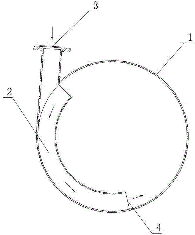
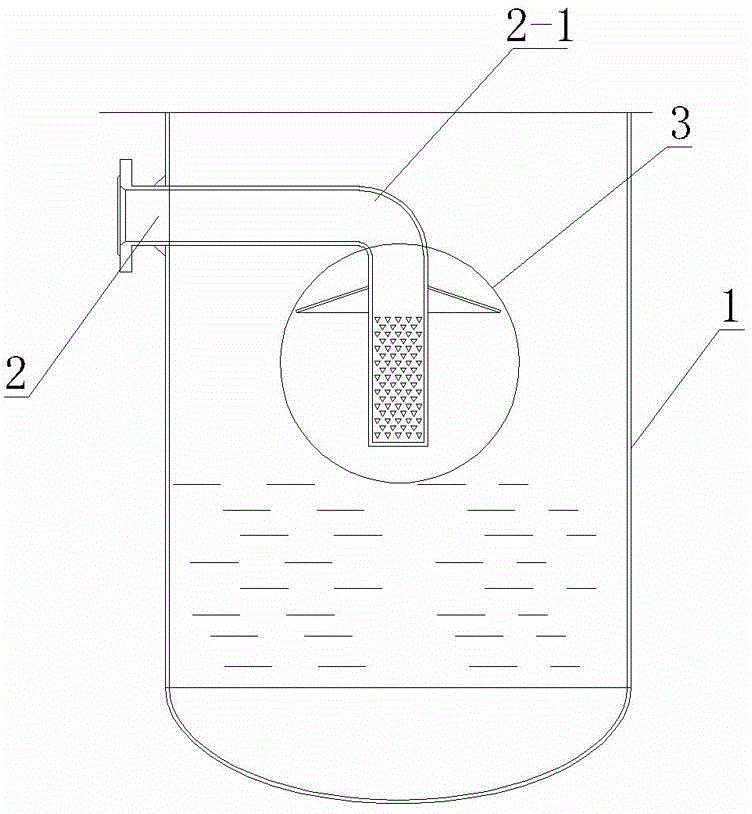
[0014] Embodiment 1: the structure of separator material distribution defoaming device provided by the present invention is as follows figure 2 and image 3 As shown, it includes a feed pipe 2 that is installed on the separator wall 1. The feed pipe 2 has a downward right-angle elbow 2-1 on the center line in the separator, and the elbow 2-1 is arranged vertically. The medium dispersing device 3 is connected, and the medium dispersing device 3 is made up of a fixedly connected tubular side wall 3-2 and a skirt-shaped outer edge 3-1, wherein the diameter of the skirt-shaped outer edge 3-1 is the diameter of the tubular side wall 3-2 top Twice the diameter, on the tubular side wall 3-2 are arranged inverted triangular spray holes 3-3, the inverted triangle is an isosceles triangle with the apex pointing down, and the number of spray holes 3-3 is calculated according to the flow volume For calculation, it is better not to spray the liquid column to the separator wall. The hori...

Embodiment 2

[0016] Embodiment 2: The structure of the material distribution and defoaming device for the separator provided by the present invention is basically the same as that of Embodiment 1, the main difference lies in the selection of structural parameters of the medium dispersion device, so the drawings are omitted. In order to adapt to a larger treatment flow, on the basis of Embodiment 1, the diameter of the skirt-shaped outer edge is increased to 3 times the diameter of the top of the tubular side wall, and the spray hole is also preferably an equilateral triangle with a side length of 10mm.

[0017] When in use, the material enters the medium dispersing device in the separator from the feed pipe, so that the spilled liquid column of the separator can be scattered more evenly, further avoiding the foam generated by splashing, which can allow larger per unit time than the previous design. The amount of feed material not only reduces the discharge of condensed water COD and the los...


PUM

PropertyMeasurementUnit
Heightaaaaaaaaaa

Abstract

The invention discloses a material distributing and defoaming device of a separator. The material distributing and defoaming device comprises a material inlet pipe, wherein the material inlet pipe penetrates through the wall of the separator; a downward elbow is formed in the material pipe in the separator; the elbow is communicated with a vertically arranged medium dispersing device; the medium dispersing device comprises a tubular side wall and a skirt-like outer edge which are fixedly connected; spraying holes are arrayed in an inverted triangle manner in the tubular side wall, wherein the inverted triangle is an isosceles triangle with the vertex angle facing down; the spraying holes are arrayed in parallel along the circumferential direction of the tubular side wall; the horizontal intervals between every two adjacent spraying holes in each row are equal; every two adjacent rows of spraying holes are staggered from each other; the skirt-like outer edge is fixed on the tubular side wall above the spraying holes. The material distributing and defoaming device of the separator has relatively high treatment capability and defoaming efficiency.

Description

technical field [0001] The invention relates to evaporation and separation equipment, in particular to a separator material distribution and defoaming device. Background technique [0002] The secondary steam generated by evaporation is usually mixed with solution droplets, especially in the forced circulation evaporator, due to the pressure of the delivery pump, the flow rate of the material entering the separator is fast, and it is easy to impact the equipment, causing the solution to splash and generate foam. , these foams will enter the next effect heat exchanger under the action of negative pressure, and will be discharged after heat exchange and condensation, resulting in the loss of products, especially for the evaporation and crystallization equipment used for sewage treatment, the existence of foams will cause the loss of condensed water COD exceeds the standard and the loss of products. [0003] In order to solve the above problems, the inventor has previously pro...

Claims


Application Information

Patent Timeline
IPC IPC(8): B01D1/30
Inventor 树晓荣
Owner JIANGSU JIATAI EVAPORATION CRYSTALLIZATION EQUIP
Why Eureka
Try Eureka