Pipe conveying machine matched with pipe processing equipment

A technology of processing equipment and pipe feeding machine, which is applied in the direction of conveyors, mechanical conveyors, transportation and packaging, etc., can solve the problems of high labor intensity and low processing efficiency, and achieve low manufacturing cost, simple structure, saving manpower and space Effect

Active Publication Date: 2014-09-03
ZHANGJIAGANG DONGDA IND TECH RES INST
View PDF6 Cites 7 Cited by
  • Summary
  • Abstract
  • Description
  • Claims
  • Application Information

AI Technical Summary

Problems solved by technology

[0002] When pipe cutting machines, pipe bending machines, belling machines, pipe shrinking machines, chamfering machines and other pipe processing equipment are fed, the pipe materials are generally fed into the processing equipment along the axial direction manually, which is labor-intensive, low processing efficiency, and difficult to process. Matching with the pipe making machine into an efficient production and processing line

Method used


Image

  • Pipe conveying machine matched with pipe processing equipment
  • Pipe conveying machine matched with pipe processing equipment

Examples


Embodiment Construction

[0024] Specific embodiments of the present invention will be described in detail below in conjunction with the accompanying drawings.

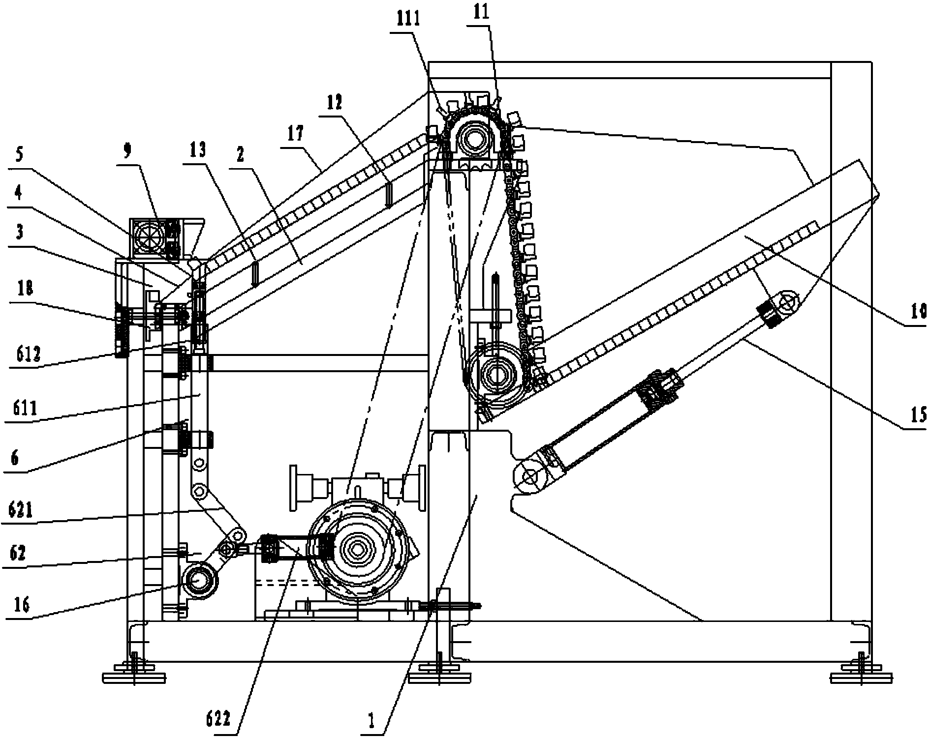
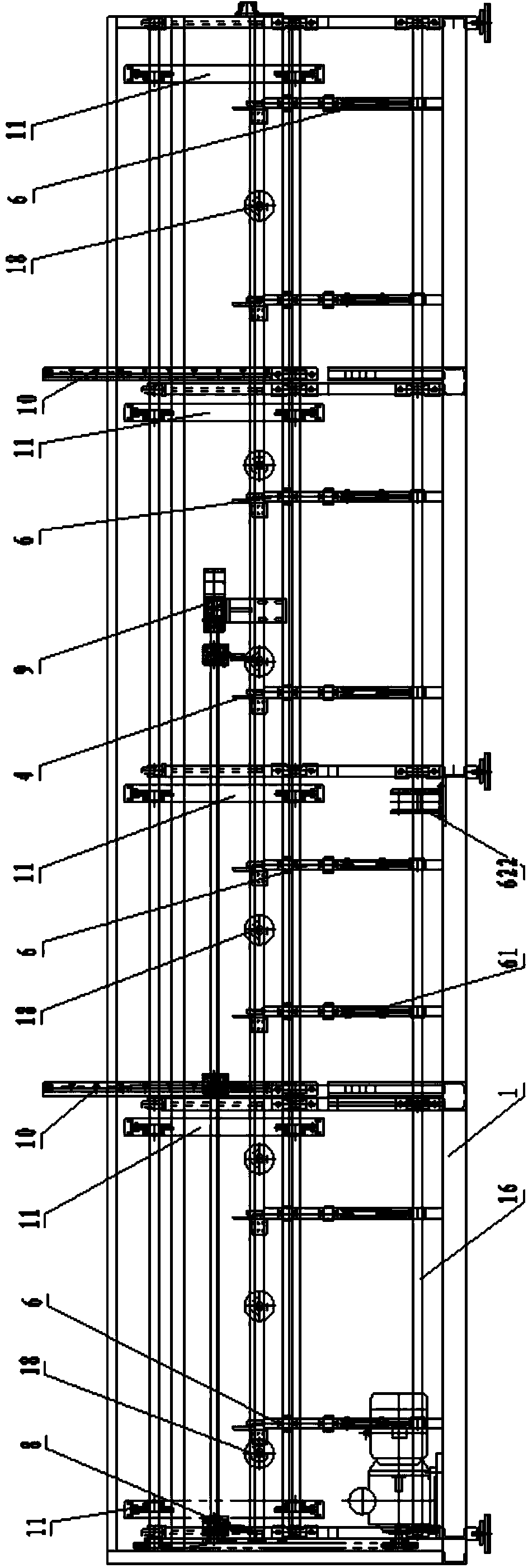
[0025] like Figure 1-2 As shown, a pipe feeding machine for supporting pipe processing equipment includes a frame 1, and the frame 1 is provided with a feeding slope 2 and a feeding groove 3, and the frame 1 is located between the feeding slope 2 and the feeding groove 3 A material guide plate 4 is provided between them. A material blocking column 5 is provided at the bottom of the feeding slope 2 . The frame 1 is provided with an upper baffle plate 17 above the feeding slope 2, and the bottom of the upper material baffle 17 is above the jacking station of the jacking rod 61 and forms a gap with the feeding slope 2 for a pipe to pass through. .

[0026] The frame 1 is provided with a jacking mechanism 6 that sends the pipe material from the feeding slope 2 to the material guide plate 4 . The jacking mechanism 6 includes at least two jacki...


PUM


Abstract

The invention discloses a full-automatic pipe conveying machine matched with pipe processing equipment. The full-automatic pipe conveying machine matched with the pipe processing equipment comprises a machine frame, wherein the machine frame is provided with a feeding inclined surface and a feeding groove, a guide plate is arranged on the machine frame and between the feeding inclined surface and the feeding groove, and a material blocking pillar is arranged at the bottom of the feeding inclined surface. The machine frame is provided with an ejection mechanism conveying pipe materials from the feeding inclined surface to the guide plate. The ejection mechanism comprises at least two ejection rods movably arranged on the machine frame in the vertical direction and a driving mechanism driving the ejection rods to move vertically, the top surface of each ejection rod is an inclined surface in the same inclining direction as the feeding inclined surface, a material sensor is arranged in the feeding groove, and a pushing part and a pushing oil cylinder for driving the pushing part are arranged at the tail end of the feeding groove.

Description

technical field [0001] The invention relates to a pipe feeding machine for supporting pipe material processing equipment. Background technique [0002] When pipe cutting machines, pipe bending machines, flaring machines, pipe shrinking machines, chamfering machines and other pipe processing equipment are fed, the pipe materials are generally fed into the processing equipment along the axial direction manually, which is labor-intensive, low processing efficiency, and difficult to process. It is matched with the pipe making machine to form an efficient production and processing line. Contents of the invention [0003] The technical problem to be solved by the present invention is to provide a fully automatic pipe feeder for supporting pipe processing equipment. [0004] In order to solve the above technical problems, the technical solution adopted in the present invention is: a pipe feeding machine for supporting pipe processing equipment, including a frame, the frame is pr...

Claims


Application Information

Patent Timeline
Patent Type & Authority Applications(China)
IPC IPC(8): B65G37/00
Inventor 贾卫峰
Owner ZHANGJIAGANG DONGDA IND TECH RES INST
Why Eureka
Try Eureka