Reducing screw displacement pile drilling tool and construction method thereof

A technology of variable-diameter piles and auger bits, which can be used in earth drilling, drilling without stripping topsoil, and drill pipes. It can solve problems such as broken piles, construction quality problems, and difficulties in hole formation, and improve pile side friction. , Good construction quality and fast construction speed

Active Publication Date: 2014-09-03
邢占东 +2
View PDF7 Cites 14 Cited by
  • Summary
  • Abstract
  • Description
  • Claims
  • Application Information

AI Technical Summary

Problems solved by technology

But all there is certain problem in above-mentioned two kinds of pile-forming methods: 1, half-screw pile pile-forming method is a kind of semi-squeezed soil pile, also will produce a certain amount of slag in the construction process, and the screw thread that this construction method pile forms can effectively improve However, in soft silt and silty soil, not only can no screw thread be formed, but also it is very easy to cause shrinkage and pile breakage, resulting in construction quality problems, and its applicability is limited to a certain extent.
2. The construction method of two-way spiral extrusion expansion pile is a kind of soil extrusion pile, which basically does not produce slag during the construction process. This construction method can effectively improve the bearing capacity of the pile through its soil extrusion effect, but limited by equipment, its cost The rock and penetrating ability is limited, and it is difficult to form holes in the dense sandy soil with the standard penetration number N>35; and the pile is cylindrical, the performance of the material under the pile is not fully utilized, and there is a certain waste of material

Method used


Image

  • Reducing screw displacement pile drilling tool and construction method thereof
  • Reducing screw displacement pile drilling tool and construction method thereof
  • Reducing screw displacement pile drilling tool and construction method thereof

Examples


Embodiment Construction

[0029] The present invention will be described in further detail below in conjunction with the accompanying drawings and specific embodiments. First of all, it should be pointed out that what is described in this section is only a preferred embodiment for implementing the present invention. Those skilled in the art can make modifications to the technical solutions described here, and these modifications will also fall within the scope of the present invention.

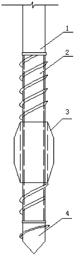
[0030] Reference attached figure 1 , a helical soil-squeezing variable-diameter pile drilling tool, comprising a hollow inner drill rod 2, the inner drill rod 2 is a cylinder with an external thread on the outer wall, and the outer part of the inner drill rod 2 is connected with a soil-squeezing body 3 with an internal thread through threads , the extruded soil body 3 is a spindle body with two thin ends and a thick middle.

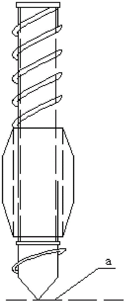
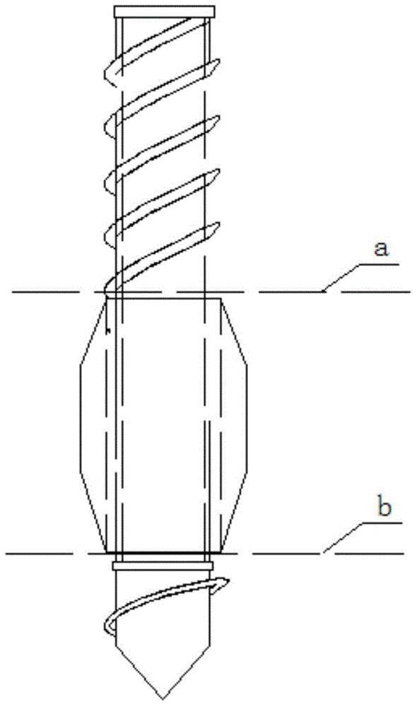
[0031] Reference attached Figure 2 to Figure 6 , a method for constructing by using the scr...


PUM


Abstract

The invention discloses a reducing screw displacement pile drilling tool and a construction method. The drilling tool comprises a hollow inner drill stem; the inner drill stem is a cylinder on the outer wall of which external threads are formed; a displacement body with internal threads is connected to the outside of the inner drill stem by use of the threads; the displacement body is a spindle body which is thin in two ends and thick in middle part. A method for carrying out construction by using the drilling tool comprises the following steps: the power head of an in-position drilling machine rotates forward and the displacement body reaches a first supporting course depth; the inner drill stem continue drilling downwards until a screw drill bit reaches in a second supporting course position; the power head rotates backwards, concrete is poured, the drilling tool is lifted, and then the screw pile body is formed; when the screw drill bit goes up to the first supporting course position, the power head rotates forwards and concrete is poured continuously, and the displacement body rotates and is lifted so that the cylindrical pile is formed; the drilling tool is pulled out and then the pile body is formed.

Description

technical field [0001] The invention belongs to the technical field of cast-in-place pile construction for construction engineering, railways, highways and bridges, and in particular relates to a drilling tool for a screw-squeezing soil variable-diameter pile and a construction method. Background technique [0002] With the rapid development of the economy, buildings are gradually developing towards high-rise, large-span and large-area directions. The loads of buildings and structures are increasing. Most of the natural foundations cannot meet the requirements of building loads. It is widely used in the basic system of engineering buildings and structures. [0003] Most of the existing cast-in-situ pile constructions follow the traditional technology, adopting the construction technology of mud retaining wall forming holes. [0004] In the traditional construction technology, the mechanical equipment used in the construction of cast-in-place piles is mainly rotary drilling ...

Claims


Application Information

Patent Timeline
Patent Type & Authority Applications(China)
IPC IPC(8): E21B17/22E21B7/30E02D5/36E02D5/56
Inventor 邢占东岳霞
Owner 邢占东
Why Eureka
Try Eureka