Wavelength demodulating device and method for fiber bragg grating sensor network

A Bragg grating and sensor network technology, which is applied in the demodulation of light, the use of optical devices to transmit sensing components, cladding optical fibers, etc., can solve the problems of slow demodulation speed, insufficient practicability, and optical power of grating reflection signals minor issues

Active Publication Date: 2014-09-03
WUHAN UNIV OF TECH
View PDF5 Cites 2 Cited by
  • Summary
  • Abstract
  • Description
  • Claims
  • Application Information

AI Technical Summary

Problems solved by technology

Traditional grating demodulation techniques include wavelength division multiplexing (WDM) technology, time division multiplexing (TDM) technology or a combination of the two. Although both WDM and TDM have been widely used, there are also obvious defects: Among them, WDM technology needs to allocate a corresponding wavelength bandwidth for each multiplexed grating, thus limiting the number of sensors in the grating array. At the same time, a relatively complex wavelength-sensitive system is required for signal demultiplexing, such as tunable Fabry-Perot filter, etc.; while TDM requires narrow pulse and high-speed devices, not only the cost is high, but also the number of sensor multiplexing is limited by the signal-to-noise ratio of the system, because the too narrow pulse makes the grating reflect the signal light low power
The above two frequency-domain interference methods introduce an acousto-optic frequency shifter into the optical fiber Sagnac ring to realize the frequency encoding of the interference signal, and both are based on the Fourier transform to realize the demultiplexing of the sensor, so they are limited by a large number of Data acquisition and calculation, demodulation speed is slow, and the practicability is insufficient

Method used


Image

  • Wavelength demodulating device and method for fiber bragg grating sensor network
  • Wavelength demodulating device and method for fiber bragg grating sensor network
  • Wavelength demodulating device and method for fiber bragg grating sensor network

Examples


Embodiment Construction

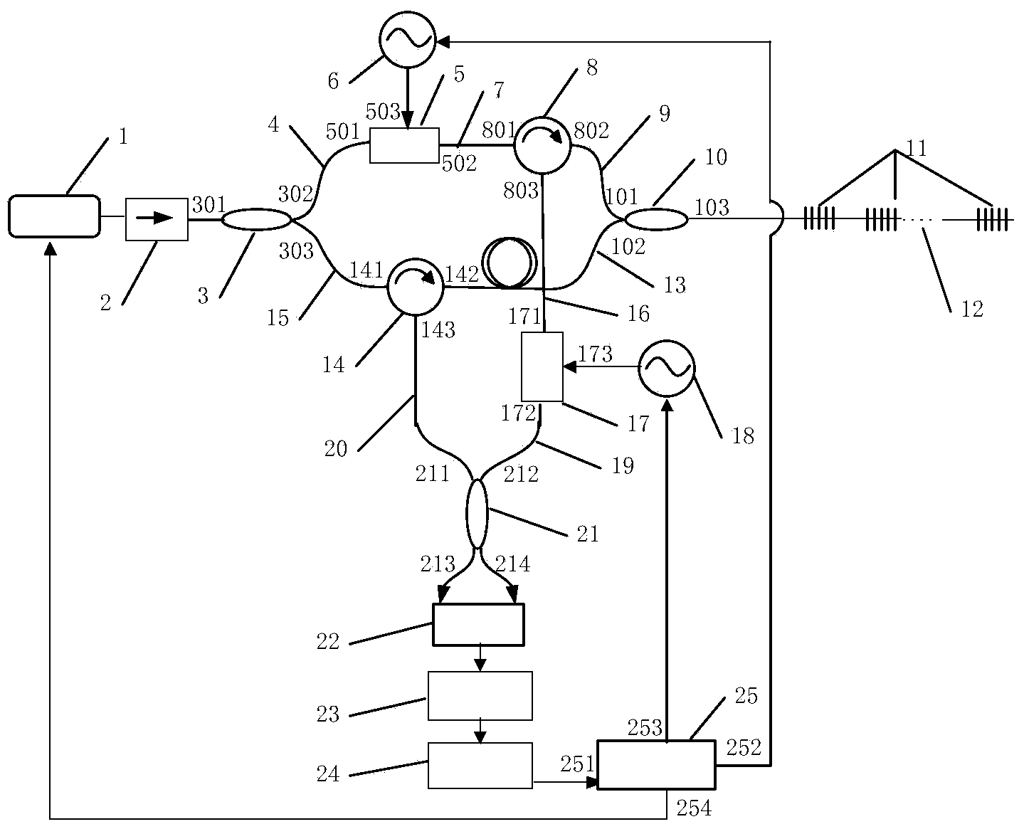
[0042] figure 1 It is a structural schematic diagram of an embodiment of the present invention, which includes a tunable narrowband light source 1, and the narrowband light output by the tunable narrowband light source 1 passes through an optical isolator 2 and then is divided into two beams of probe light by a first optical fiber coupler 3, which are respectively the first a beam of probe light and a second beam of probe light;

[0043] The first probe light enters the first optical frequency shifter 5 through the first connecting optical fiber 4 to produce a frequency shift, and then enters the first port 801 of the first optical circulator 8 through the second connecting optical fiber 7, and the second optical circulator of the first optical circulator The probe light emitted by the second port 802 is incident on the first port 101 of the second fiber coupler 10 through the third connecting optical fiber 9;

[0044] The second probe light enters the first port 141 of the s...


PUM


Abstract

The invention provides a wavelength demodulating device and method for a fiber bragg grating sensor network. According to the wavelength demodulating device and method, optical frequency shifters are utilized for modulating frequencies of two beams of interference light respectively. The method comprises the steps that the two optical frequency shifters are adopted to conduct independent linear frequency modulation on two ways of detection light, tuning of the bragg grating reflection light interference beat frequency is achieved by adjusting the frequency modulation difference value of the two optical frequency shifters, bragg grating reflected signals to be demodulated are obtained through an electronic band-pass filter, and the bragg grating sensor network is demodulated under the situation of spectral overlapping. Due to the fact that a Fourier transform algorithm used in an existing traditional frequency domain interference method does not need to be adopted, the real-time performance and the response speed of a system are improved, complexity of a system signal processing device is reduced, and then the system cost is reduced.

Description

technical field [0001] The invention belongs to the technical field of optical fiber sensing, and in particular relates to a wavelength demodulation device and method for an optical fiber Bragg grating sensing network. Background technique [0002] Fiber Bragg grating (FBG) has become an important device for optical fiber sensing due to its unique advantages such as internal sensitivity of optical fiber, wavelength coding, and easy networking. Optical fiber Bragg grating sensing network is widely used in optical fiber quasi-distributed sensing, such as health monitoring of railways, bridges, dams and large equipment, fire monitoring of tunnels and oil depots, etc. Traditional grating demodulation techniques include wavelength division multiplexing (WDM) technology, time division multiplexing (TDM) technology or a combination of the two. Although both WDM and TDM have been widely used, there are also obvious defects: Among them, WDM technology needs to allocate a correspondi...

Claims


Application Information

Patent Timeline
Patent Type & Authority Applications(China)
IPC IPC(8): G02F2/00G02B6/02G02B6/26G01D5/26G01D5/353
Inventor 姜德生许儒泉
Owner WUHAN UNIV OF TECH
Why Eureka
Try Eureka